Cell stack for a flowing electrolyte battery

a technology of flowing electrolyte and cell stack, which is applied in the field of batteries, can solve the problems of lead-acid batteries that have limitations in terms of performance and environmental safety, lead-acid batteries are also environmentally hazardous, and typical lead-acid batteries have very short lifetimes in hot, so as to improve the structural robustness of the cell stack, reduce manufacturing costs, and increase the battery size

Active Publication Date: 2012-10-23
REDFLOW PTY LTD
View PDF17 Cites 6 Cited by
  • Summary
  • Abstract
  • Description
  • Claims
  • Application Information

AI Technical Summary

Benefits of technology

[0015]Therefore, an object of the present invention is to overcome or alleviate one or more limitations of the prior art including providing improved structures for circulating electrolyte through battery cells to reduce manufacturing costs and to improve structural robustness of a cell stack for a flowing electrolyte battery, but without increasing a battery size.
[0016]A further object of the present invention is to provide an improved electrode plate to reduce manufacturing costs and to improve structural robustness of a cell stack for a flowing electrolyte battery.SUMMARY OF THE INVENTION
[0020]Optionally, the capillary tube in each half cell provides a high electrical resistance between electrolyte at the first end and electrolyte at the second end.

Problems solved by technology

However, lead-acid batteries have limitations in terms of performance and environmental safety.
Typical lead-acid batteries often have very short lifetimes in hot climate conditions, especially when they are occasionally fully discharged.
Lead-acid batteries are also environmentally hazardous, since lead is a major component of lead-acid batteries and can cause serious environmental problems during manufacturing and disposal.
However, manufacturing flowing electrolyte batteries can be more difficult than manufacturing lead-acid batteries.
This can be problematic as shunt currents can flow through the electrolyte circulation path from one series-connected cell to another causing energy losses and imbalances in the individual charge states of the cells.
Another problem of flowing electrolyte batteries is a need for a uniform electrolyte flow rate in each cell in order to supply chemicals evenly inside the cells.
However, because electrolyte often has an oily and gaseous multiphase nature, and because of structural constraints on the cells, uniform flow rates are often not achieved.
Such a delicate connection apparatus is not only difficult to manufacture, but is also prone to damage during assembly and use.
An over supply of electrolyte to any section of the electrode will cause a reduction in the efficiency of the battery.
An under supply of electrolyte to any section of the electrode can permit dendrite formation which may lead to permanent damage to the separator and shorting between cells.

Method used


Image

  • Cell stack for a flowing electrolyte battery
  • Cell stack for a flowing electrolyte battery
  • Cell stack for a flowing electrolyte battery

Examples


Embodiment Construction

[0047]Embodiments of the present invention comprise a cell stack for a flowing electrolyte battery. Elements of the invention are illustrated in concise outline form in the drawings, showing only those specific details that are necessary to understanding the embodiments of the present invention, but so as not to clutter the disclosure with excessive detail that will be obvious to those of ordinary skill in the art in light of the present description.

[0048]In this patent specification, adjectives such as first and second, left and right, front and back, top and bottom, etc., are used solely to define one element or method step from another element or method step without necessarily requiring a specific relative position or sequence that is described by the adjectives. Words such as “comprises” or “includes” are not used to define an exclusive set of elements or method steps. Rather, such words merely define a minimum set of elements or method steps included in a particular embodiment...


PUM

PropertyMeasurementUnit
polarityaaaaaaaaaa
lengthaaaaaaaaaa
weight ratioaaaaaaaaaa

Abstract

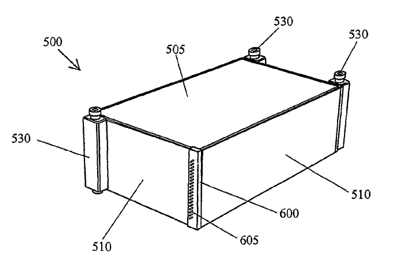
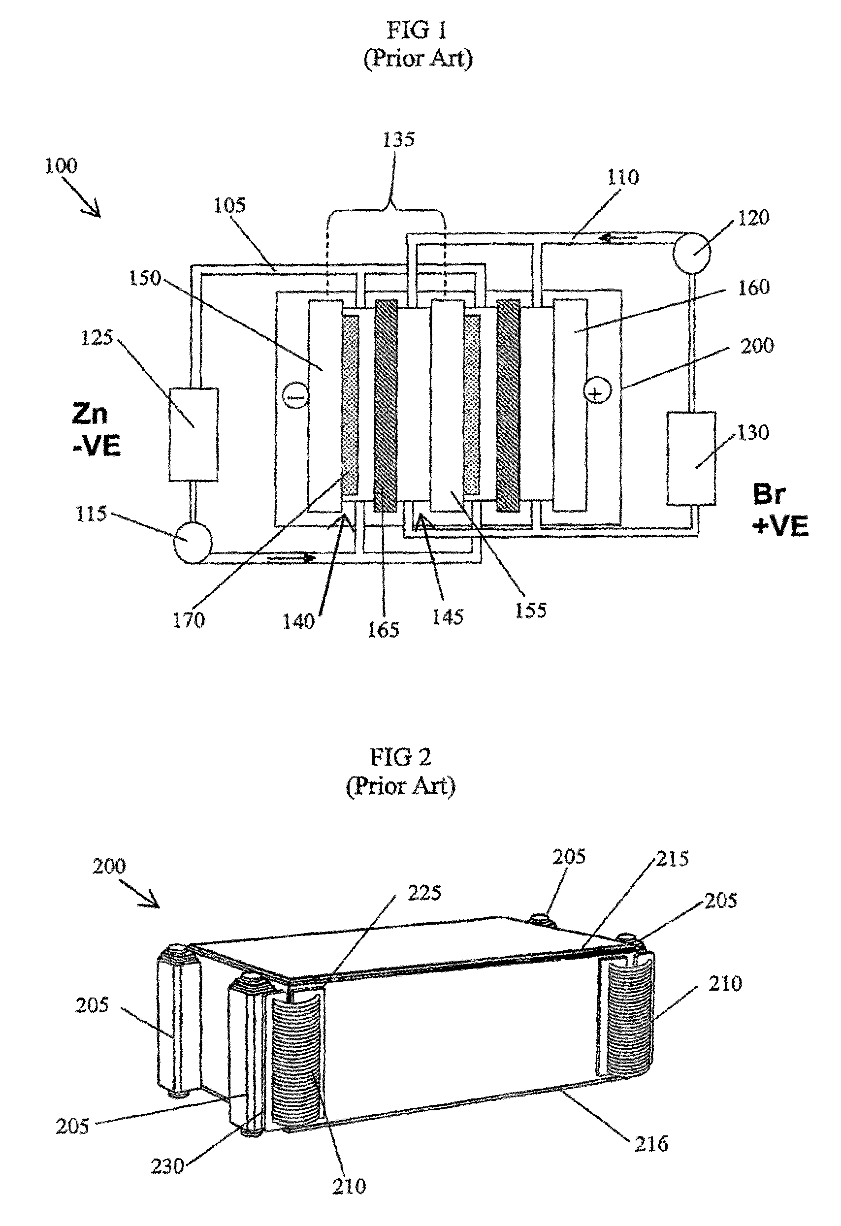
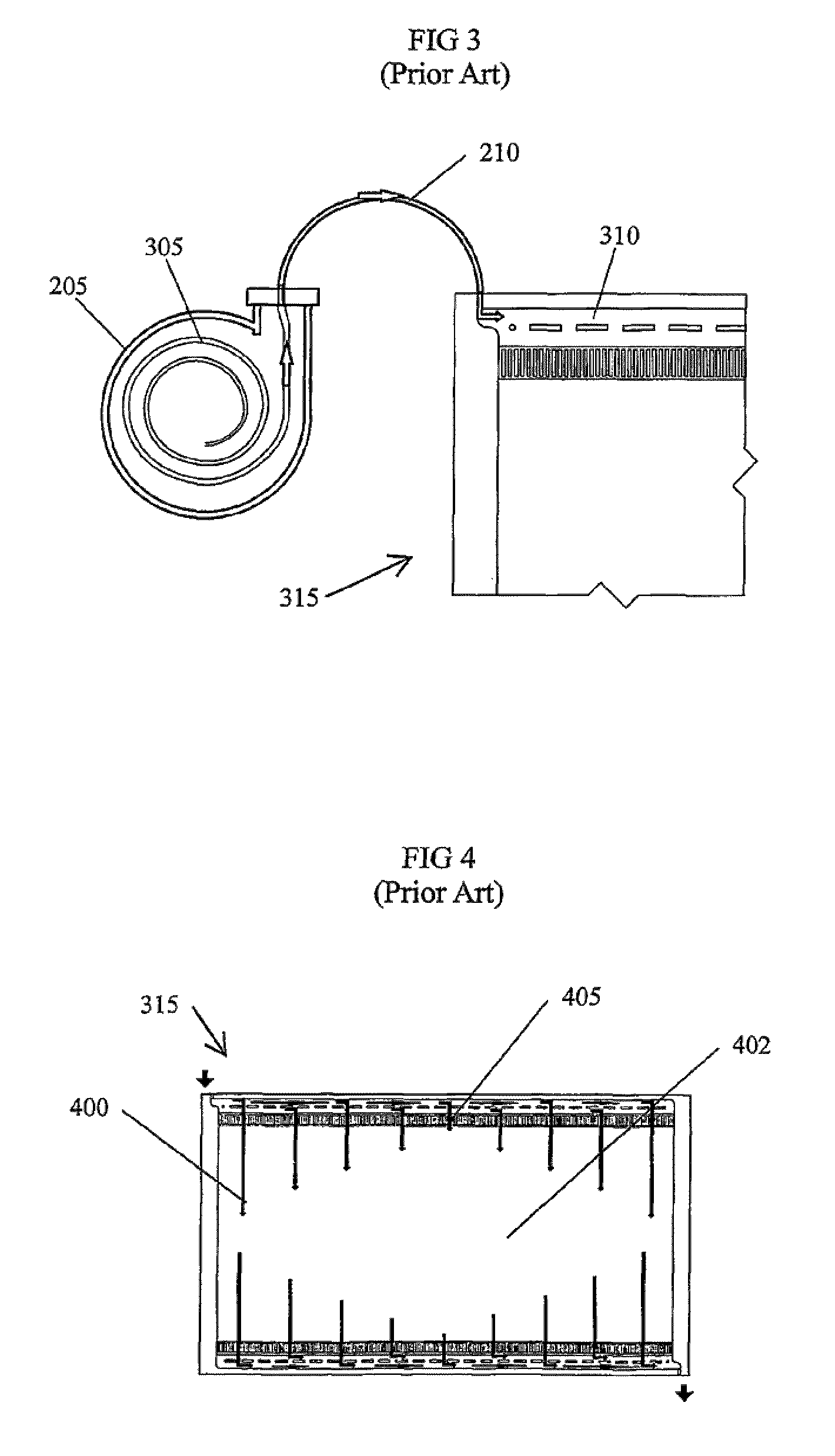
A cell stack (700) as provided enables a flowing electrolyte battery to have a reduced size and weight. The cell stack (700) includes a casing having a positive polarity end and a negative polarity end. A plurality of half cells (805) are inside the casing, and each half cell (805) includes an electrode plate (705), an adjacent separator plate (715), and at least one capillary tube (727) positioned between the electrode plate (705) and the adjacent separator plate (715). The capillary tube (727) has a first end extending outside of the half cell (805) and a second end located inside the half cell (805). At least one manifold (530) is in hydraulic communication with a plurality of capillary tube ends including the first end of the capillary tube (727) in each half cell (805). The capillary tube (727) in each half cell (805) enables electrolyte to circulate through the plurality of half cells (805) via the at least one manifold (530).

Description

[0001]This is a U.S. national phase entry of International application PCT / AU2008 / 000353, filed 13 Mar. 2008, published WO 2008 / 116248, which claims priority to Australian application 2007901653 filed 28 Mar. 2007.FIELD OF THE INVENTION[0002]The present invention relates to batteries. In particular, although not exclusively, the invention relates to a flowing electrolyte battery having a cell stack including capillary tubes.BACKGROUND TO THE INVENTION[0003]Batteries used in stand alone power supply systems are commonly lead-acid batteries. However, lead-acid batteries have limitations in terms of performance and environmental safety. Typical lead-acid batteries often have very short lifetimes in hot climate conditions, especially when they are occasionally fully discharged. Lead-acid batteries are also environmentally hazardous, since lead is a major component of lead-acid batteries and can cause serious environmental problems during manufacturing and disposal.[0004]Flowing electrol...

Claims


Application Information

Patent Timeline
Patent Type & Authority Patents(United States)
IPC IPC(8): H01M2/38H01M2/14H01M6/04H01M10/26H01M50/77H01M10/36
CPCH01M2/40H01M10/365H01M12/085H01M8/188H01M10/4214Y02E60/528Y02E60/10Y02E60/50H01M50/77
Inventor WINTER, ALEXANDER RUDOLF
Owner REDFLOW PTY LTD
Why Eureka
Try Eureka