Electricity accumulating device

a technology of accumulating devices and capacitors, applied in the direction of electric variable regulation, process and machine control, instruments, etc., can solve the problems of shortening the life of the capacitor, insufficient acceleration, and the possibility of changing the characteristics of the battery, so as to achieve the effect of simple operation and extended life of the capacitor

Active Publication Date: 2012-10-23
PANASONIC CORP
View PDF8 Cites 11 Cited by
  • Summary
  • Abstract
  • Description
  • Claims
  • Application Information

AI Technical Summary

Benefits of technology

[0015]The present invention provides an electricity accumulating device having capacitors whose life is extended accurately by a simple operation.
[0017]According to the electricity accumulating device of the present invention, the control circuit calculates the absolute value (ΔVi) of the difference between the two voltages (V1i and V2i) measured at different times from each other across each of the capacitors, and determines the balanced voltage (Vri) therefrom while the capacitors are not being charged or discharged. This eliminates the need to calculate the capacitance C or the internal resistance R while the capacitors are being charged at a constant current as in the conventional electricity accumulating devices. This also eliminates the need to control the determination of the balanced voltage from the average of the degree of degradation. As a result, the life of the capacitors can be extended by a simpler operation than in the conventional electricity accumulating devices.

Problems solved by technology

Such batteries, however, are likely to change their characteristics or to be degraded while being rapidly charged or discharged with a large current.
This, however, sometimes makes acceleration insufficient.
If charged without considering this, capacitors may be degraded, thereby shortening their life.
Therefore, the smaller the differences, the greater the degree of degradation.
As a result, the electricity accumulating device has a long life.
The above-described conventional electricity accumulating device, however, is required to perform the following complex operations while capacitors 501 are being charged with a constant current.

Method used


Image

  • Electricity accumulating device
  • Electricity accumulating device
  • Electricity accumulating device

Examples


first exemplary embodiment

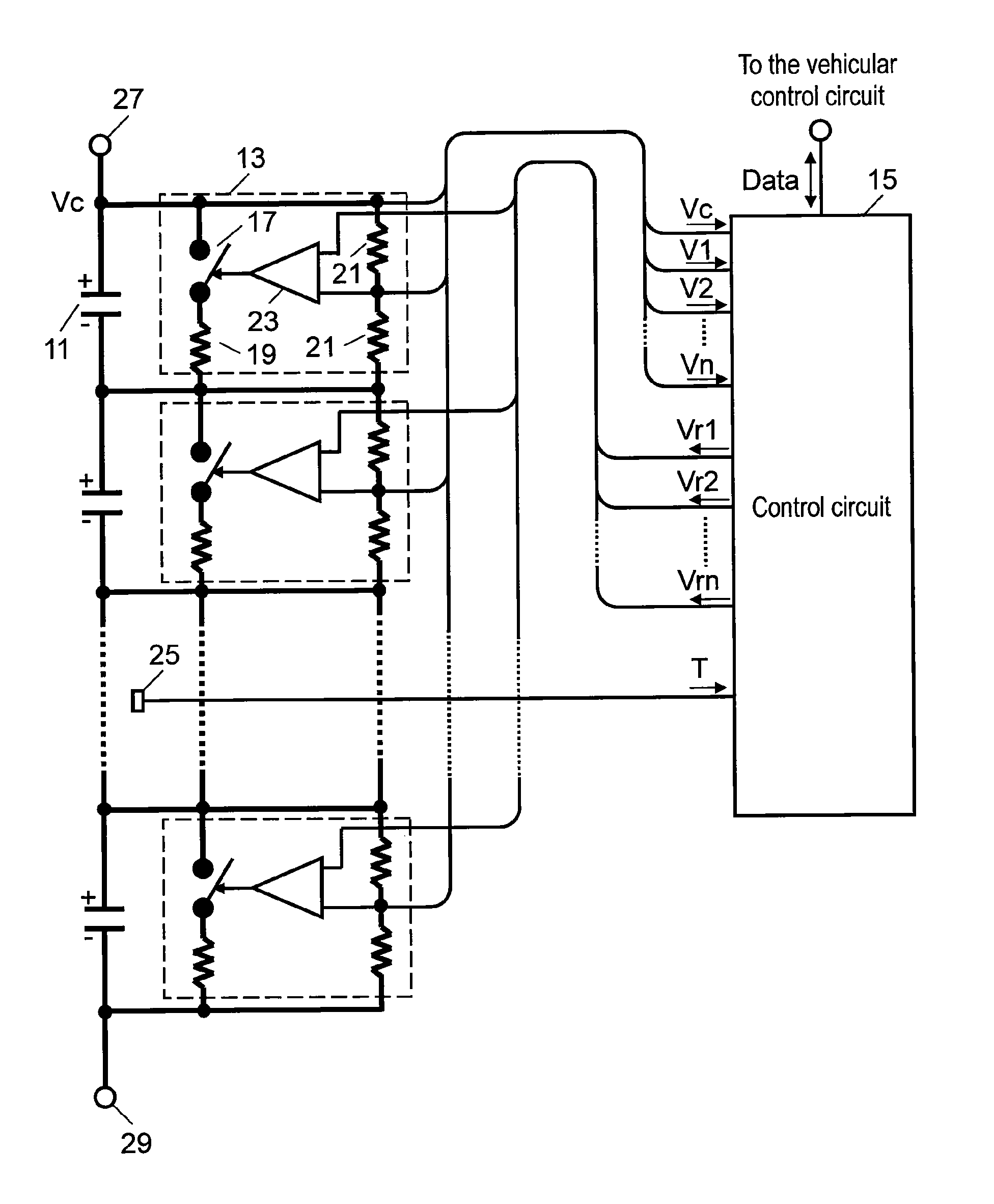
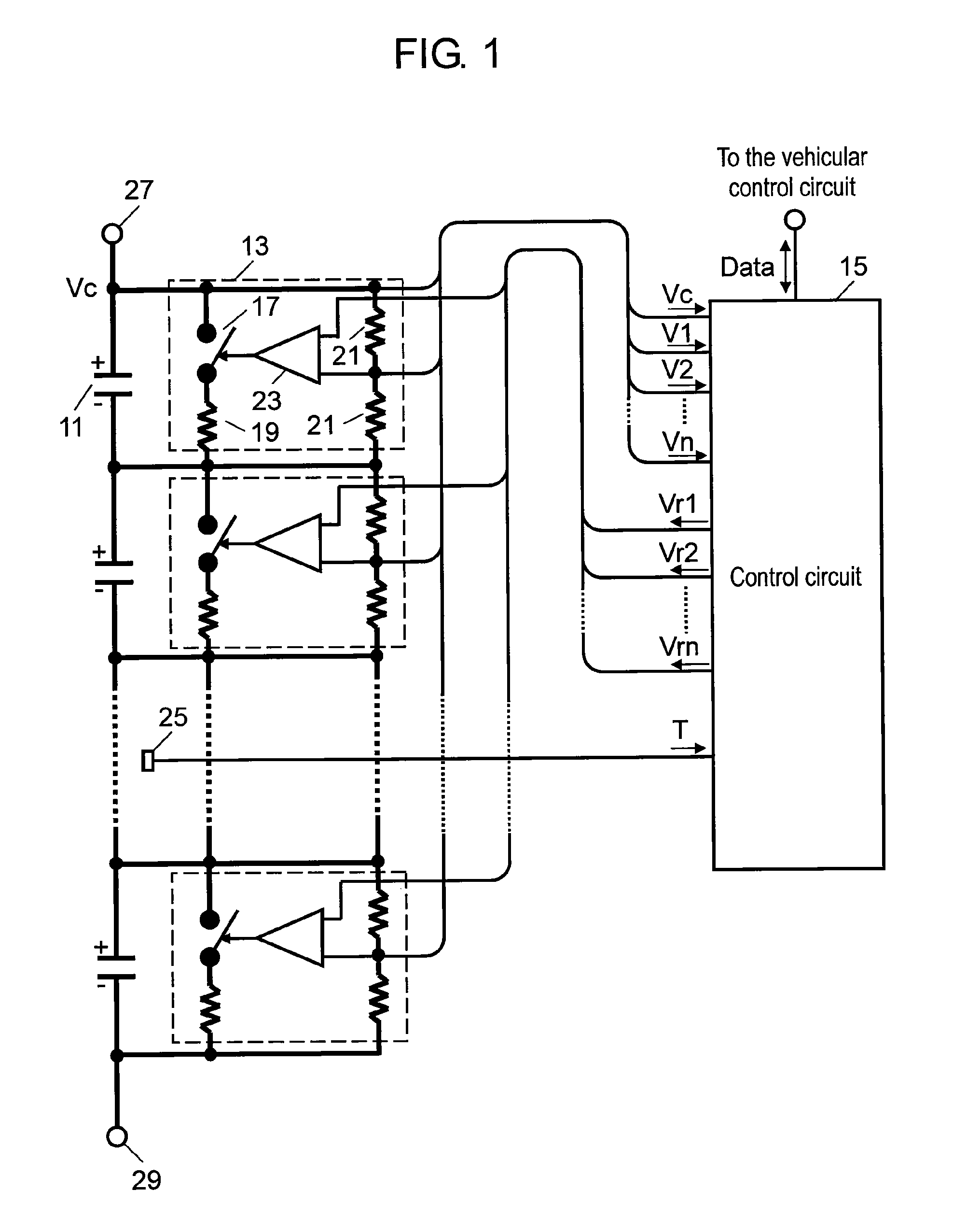
[0036]FIG. 1 is a block circuit diagram of an electricity accumulating device according to a first exemplary embodiment of the present invention. As shown in FIG. 1, the electricity accumulating device includes capacitors 11 connected in series. In the drawing, thick lines represent electrical wires, and thin lines represent signal wires. Capacitors 11 in the present first exemplary embodiment are electric double layer capacitors having a large capacitance. Capacitors 11 may alternatively be connected in series-parallel according to the power specification required. In this case, capacitors connected in parallel are treated as one capacitor 11 so as to make them have an equivalent circuit of capacitors 11 shown in FIG. 1. Therefore, the following description is based on the assumption that each capacitor 11 can be either one or a plurality of capacitors connected in parallel. It is possible that the end terminals of series-connected capacitors 11 in the electricity accumulating devi...

second exemplary embodiment

[0070]FIG. 4 is a flowchart showing a process for determining the balanced voltage of each capacitor in an electricity accumulating device according to a second exemplary embodiment of the present invention. The electricity accumulating device of the present second exemplary embodiment has the same structure as that of the first exemplary embodiment shown in FIG. 1, and hence, the description thereof will be omitted. The present second exemplary embodiment is characterized by its operation, which will be described in detail as follows.

[0071]In FIG. 4, when the vehicle is started or in operation, control circuit 15 reads the present voltage V1i across each capacitor 11 at a time t1, which is during the non-charge-or-discharge period of capacitors 11, and stores them in a memory embedded in control circuit 15. In this case, the voltage V1i across each capacitor 11 is subjected to temperature correction in the same manner as in the first exemplary embodiment. The time t1 is not stored ...

third exemplary embodiment

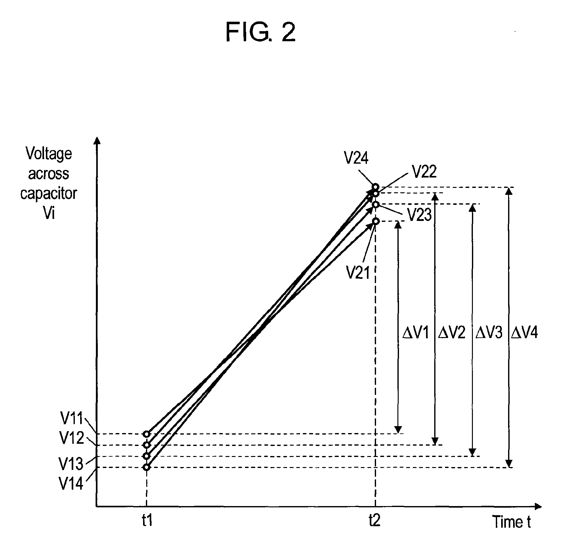
[0086]FIG. 5 is a graph showing the change in the voltage across each capacitor from time t1 to time t2 in an electricity accumulating device according to a third exemplary embodiment of the present invention.

[0087]The electricity accumulating device of the present third exemplary embodiment has the same structure as that of the first exemplary embodiment shown in FIG. 1, and hence, the description thereof will be omitted. The present third exemplary embodiment is characterized by its operation, which will be described in detail as follows. In FIG. 5, the horizontal axis represents the time “t”, and the vertical axis represents the voltage Vi across each capacitor 11. In the case of a hybrid vehicle, several hundred capacitors 11 are connected in series as mentioned above, however, in the following description, only four capacitors 11 are connected in series for easier explanation as in the first exemplary embodiment. Thus, the number “n” of capacitors 11 is 4, and the subscript “i”...


PUM


Abstract

An electricity accumulating device includes capacitors connected in series, balanced voltage adjusting portions connected to the capacitors respectively, and a control circuit connected to the balanced voltage adjusting portions. The control circuit performs the following operations: measuring two voltages at different times from each other across each capacitor during the non-charge-or-discharge period of the capacitors by using the balanced voltage adjusting portions; calculating the absolute value of the difference between the two voltages; determining the balanced voltage of each of the capacitors according to the absolute value; and controlling the balanced voltage adjusting portions to make the voltage across each capacitor a balanced voltage.

Description

[0001]THIS APPLICATION IS A U.S. NATIONAL PHASE APPLICATION OF PCT INTERNATIONAL APPLICATION PCT / JP2009 / 000004.TECHNICAL FIELD[0002]The present invention relates to an electricity accumulating device having capacitors for storing and discharging electric power.BACKGROUND ART[0003]With increasing concern for the environment in recent years, electric and hybrid cars, which are wholly or partially driven by a motor, are growing in popularity. In these cars (hereinafter, vehicles), the electric power of the motor is supplied from a battery. Such batteries, however, are likely to change their characteristics or to be degraded while being rapidly charged or discharged with a large current. To avoid this, restrictions are imposed on the current supplied to the motor when the driver tries to accelerate too fast. This, however, sometimes makes acceleration insufficient.[0004]To overcome this problem, there have been proposed vehicles having both a battery and capacitors with rapid charging-d...

Claims


Application Information

Patent Timeline
Patent Type & Authority Patents(United States)
IPC IPC(8): H02J7/00H02M3/18
CPCH02J7/0016H02J7/345Y02T10/7055H02J7/0014Y02T10/70
Inventor KAKIUCHI, KIMIYASU
Owner PANASONIC CORP
Why Eureka
Try Eureka