Scan element for use in scanning light and method of making the same

a scanning element and light beam technology, applied in the direction of optics, dynamo-electric machines, instruments, etc., can solve the problems of unbalanced structure, unbalanced hinges, unwanted tilting or drooping of scan mirrors,

Active Publication Date: 2012-10-23
METROLOGIC INSTR
View PDF147 Cites 788 Cited by
  • Summary
  • Abstract
  • Description
  • Claims
  • Application Information

AI Technical Summary

Problems solved by technology

Conventional hinge-based scan elements are formed from cantilevered beams of plastic film or other flexible materials and are not balanced structures.
Several such scan elements are described in U.S. Pat. No. 6,173,895, which suffer from unwanted tilting or drooping of the scan mirror when held in different orientations due to the effects of gravity, especially if the scan mirror and moving magnet are large.
Further, flexible film hinges can become permanently distorted if the device is dropped or otherwise exposed to rough handling.
Such distortion produces shifted scan lines or scan lines that are no longer straight.
Shaft-based scan elements, such as described in U.S. Pat. No. 7,420,721 B2, are also prone to wobble of the scan mirror induced by gravity or operator movement when used in portable hand held applications.
The above-described drawbacks are exacerbated by the use of large scan mirrors required for long range scanning.
The pole piece generates a magnetic bias that can tilt the scan mirror or cause unwanted forces, which result in undesirable speed perturbations of the scan line.
Thus, tedious adjustment is needed to ensure proper operation of the scan element, and may be subject to error.
Further drawbacks associated with conventional scan elements are radical bursts of acceleration and deceleration of the scan mirror, which distort the timing of light signals reflected from a barcode target.
Distortion often occurs when a pulse of current, such as a short duty cycle square wave, is used as a drive waveform, especially at non-resonant frequencies.

Method used


Image

  • Scan element for use in scanning light and method of making the same
  • Scan element for use in scanning light and method of making the same
  • Scan element for use in scanning light and method of making the same

Examples


second embodiment

[0039]An alternate method of forming the elastomeric supports 14 will now be described. FIG. 4 shows a substrate 70, in accordance with the invention, preferably formed from a non-magnetic material, such as phosphor bronze or beryllium copper alloy. Holes 72a and 72b are etched through the substrate 70. The holes 72a, 72b are preferably oblong in shape, but may be etched having other known shapes. Alternatively, the substrate 70 may be molded to form the holes 72a, 72b. Surrounding the holes 72a, 72b are respective first oblong shaped land areas 73a, 73b followed by partially etched second oblong areas 71a, 71b. The second oblong areas 71a, 71b are preferably etched half way through a thickness of the substrate 70.

[0040]Pockets 16, 17 formed in the surface 13a of the flange 13 (i.e., FIG. 1) are preferably shaped to match the holes 72a, 72b in the substrate 70. The pockets 16, 17 are filled evenly with liquid RTV silicone elastomeric compound. Once the pockets 16, 17 are filled, sub...

third embodiment

[0042]FIG. 5 illustrates the present invention wherein a bobbin 80, preferably formed of molded plastic, includes two molded flexible inserts 81a, 81b preferably formed of injection molded silicone rubber. FIG. 6 shows a cross-sectional view of the bobbin 80 with a flange 82. Molded inserts 81a, 81b each preferably include a shoulder 83a, 83b that anchors the respective inserts 81a, 81b into the bobbin flange 82. Atop the inserts 81a, 81b are further mounting ribs 84a, 84b, which may be shaped, for example, to fit the holes 72a, 72b of the mounting substrate 70 in FIG. 4. Mounting features 84a, 84b are preferably secured to the holes 72a, 72b using liquid adhesive (such as liquid silicone RTV resin), but may also be secured by a mechanical lock fitting or the like.

fourth embodiment

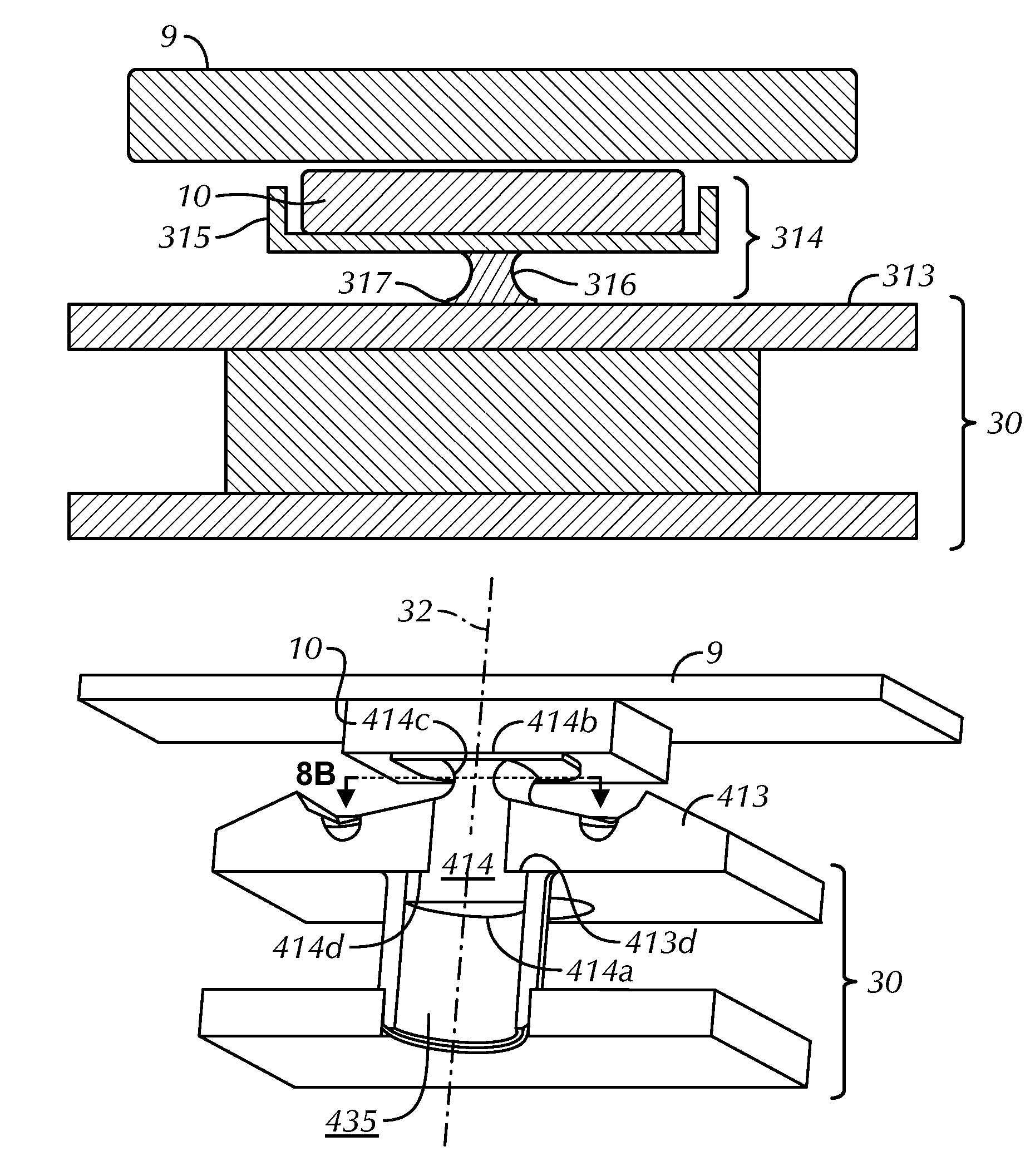
[0043]FIG. 7 shows the present invention wherein an elastomeric support 314 is shaped to hold the magnet 10 within a pocket 315 integrally formed as part of the support 314. A middle portion 316 of the support 314 flexes as described above in other embodiments, and a base portion 317 of the support 314 may be attached to a flange 313 of the bobbin 30 using anchoring methods described above.

[0044]In a preferred embodiment, the base portion 317 of the elastomeric support 314 is molded into bobbin flange 313 to firmly anchor the support 314, thereby creating a high immunity to detachment damage resulting from drops or the like. Molded insert 81a and shoulder 83a (FIG. 6) show an exemplary form of anchoring. The magnet 10 is preferably glued into the pocket 315, but may also be mechanically pressed or locked into the pocket 315. If the elastomeric support 314 is molded from silicone rubber, then the magnet 10 may be glued using liquid RTV silicone to form an exceptionally strong bond. T...


PUM

PropertyMeasurementUnit
distanceaaaaaaaaaa
magnetizationaaaaaaaaaa
areaaaaaaaaaaa

Abstract

A scan element includes a bobbin having a central axis about which is wound an electromagnetic wire coil and having a flange oriented generally transverse to the central axis. At least one elastomeric support has a first end coupled to the flange. A permanent magnet has first and second surfaces, a central axis, and a magnetization direction oriented generally transverse to the central axis of the permanent magnet. The magnet is supported by a second end of the elastomeric support. A mirror has a central axis and is mounted on the second surface of the magnet. The central axes of the mirror and magnet are coaxial with the central axis of the bobbin. The elastomeric support provides a return force when the magnet and the mirror are rotated at an angle from the central axis during energization of the electromagnetic wire coil.

Description

BACKGROUND OF THE INVENTION[0001]An embodiment of the present invention relates generally to a light beam scanning element, and more particularly, to a light beam scanning element having at least one elastomeric support, and methods of manufacturing the same.[0002]In laser-based barcode scanning equipment, and particularly in portable laser-based barcode scanning equipment, a scan component is used to dither a mirror. The moving mirror is used to sweep a laser beam across a barcode target to be read. This component is often called a scan element. A scan element is a critical moving component in portable laser-based barcode readers. Desirable attributes for a scan element are small size, ruggedness, energy efficiency, freedom from beam shifting when held in different orientations, and immunity to unwanted motions of the scan beam when held by an operator.[0003]Conventional hinge-based scan elements are formed from cantilevered beams of plastic film or other flexible materials and are...

Claims


Application Information

Patent Timeline
Patent Type & Authority Patents(United States)
IPC IPC(8): G02B26/08
CPCG02B26/105H02K33/16Y10T29/49009
Inventor PLESKO, GEORGE A.
Owner METROLOGIC INSTR
Why Eureka
Try Eureka