Locking assembly for locking an electronics card to a rack

a technology for locking assemblies and electronics cards, which is applied in the direction of electrical apparatus, electrical apparatus casings/cabinets/drawers, support structure mounting, etc., can solve the problems of not enabling the backplane connectors and electronics cards to be mounted on the rack back plate accurately positioned

Inactive Publication Date: 2012-10-23
RADIALL SA
View PDF13 Cites 13 Cited by
  • Summary
  • Abstract
  • Description
  • Claims
  • Application Information

AI Technical Summary

Benefits of technology

[0034]The invention makes it possible, amongst other things, to compensate the continuous forces that act between the electronics card and the rack.
[0084]These keying means may be pegs or coding keys, and incorporating connectors with the rack back plate may also facilitate mounting of the card connectors and of the rack back plate connectors in any order.

Problems solved by technology

Known solutions for floatingly mounted rack backplane connectors generally present the defect of the connector not touching the rack back plates, thereby giving rise to gaps that encourage leakage of electromagnetic interference.
Furthermore, a locking system for locking the daughter electronics card to the rack that is incorporated in a rack backplane connector may present the drawbacks of being difficult to access for disconnection, of not providing clear visibility of a good connection, of not coping with problems of coupling depth when a plurality of connectors are mounted on the same electronics card, or indeed of not enabling the electronics card as a whole to be stiffened, which can give rise to problems with respect to the vibration performance of the electronics card in severe-environment applications, and of not enabling the rack backplane connectors and the electronics card to be mounted in any order.
Locking merely by screw fastening does not make it possible to take up longitudinal clearances directly in the event of the rack having multiple connectors, and it does not make it simple to control the coupling force applied to the connectors.
Furthermore, prismatic slideway systems do not make it possible to overcome continuous coupling forces.
Nevertheless, such a floating connection system can require resilient elements that are very stiff, with having movement strokes of the order of several millimeters.
Springs that satisfy such conditions are relatively bulky compared with the dimensions of connectors.
Furthermore, incorporating resilient elements in rack backplane connectors can make them more complex, giving rise to an increase in the sizes of the plates of connectors in order to house the resilient elements and the spring-retaining system.
Finally, a floating mount for connectors in a rack can lead to the connectors not pressing against the metal plate at the back of the rack, thereby leaving openings that lead to leakage of electromagnetic interference (EMI).
Nevertheless, such locking systems do not provide permanent compensation for forces tending towards disconnection, which forces are generated by sealing systems, and those locking systems are unsuitable for compensating longitudinal clearances that are too great.

Method used


Image

  • Locking assembly for locking an electronics card to a rack
  • Locking assembly for locking an electronics card to a rack
  • Locking assembly for locking an electronics card to a rack

Examples


Embodiment Construction

[0090]First embodiments of a locking assembly are described with reference to FIGS. 1 to 7.

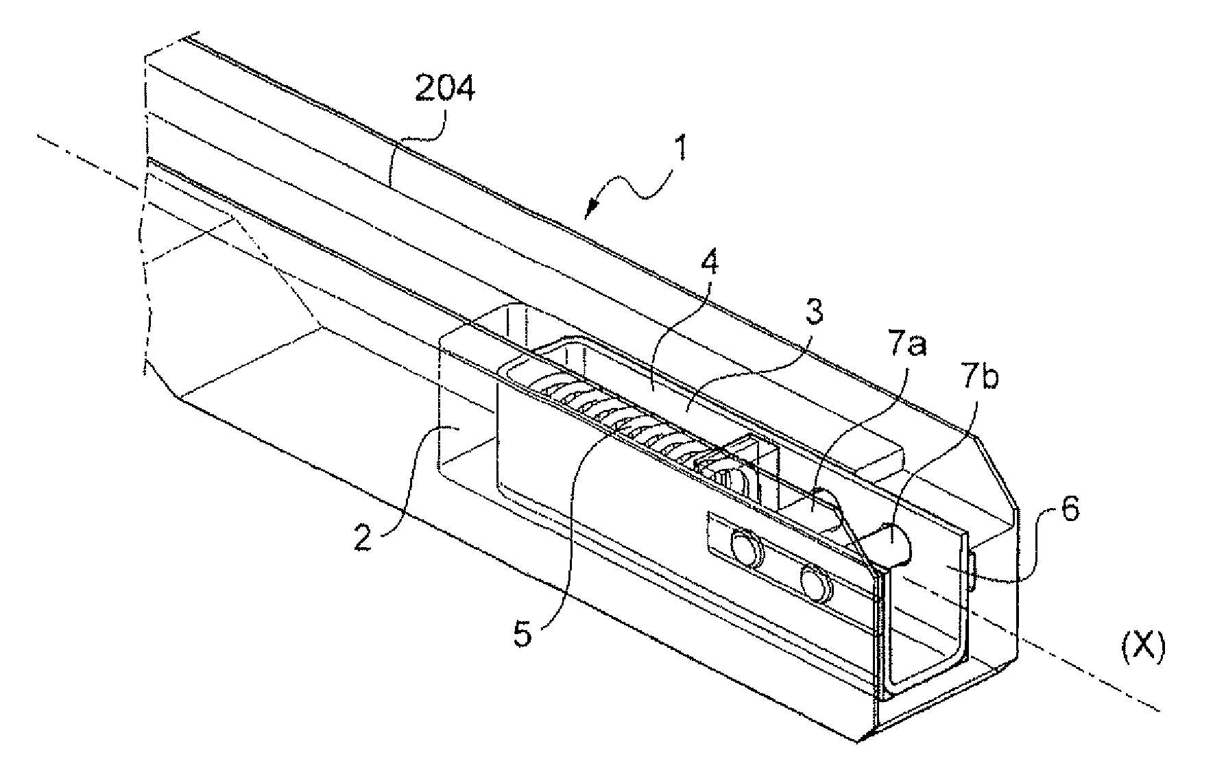
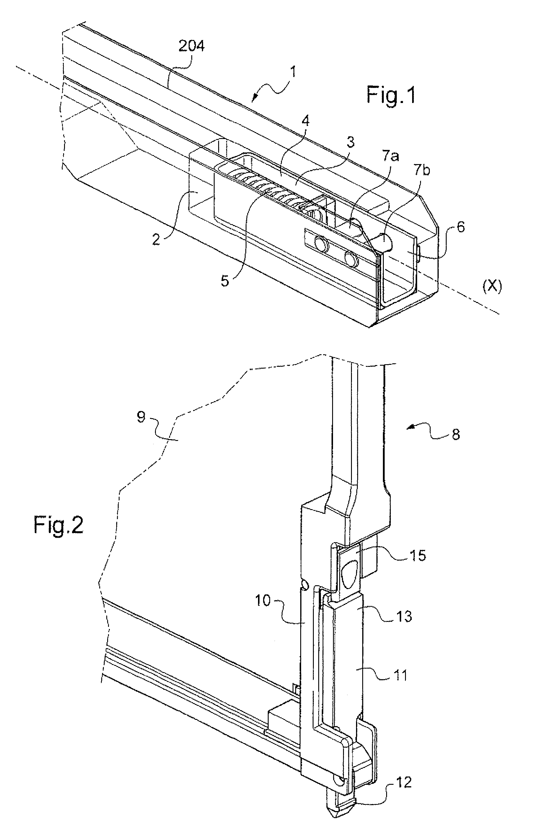
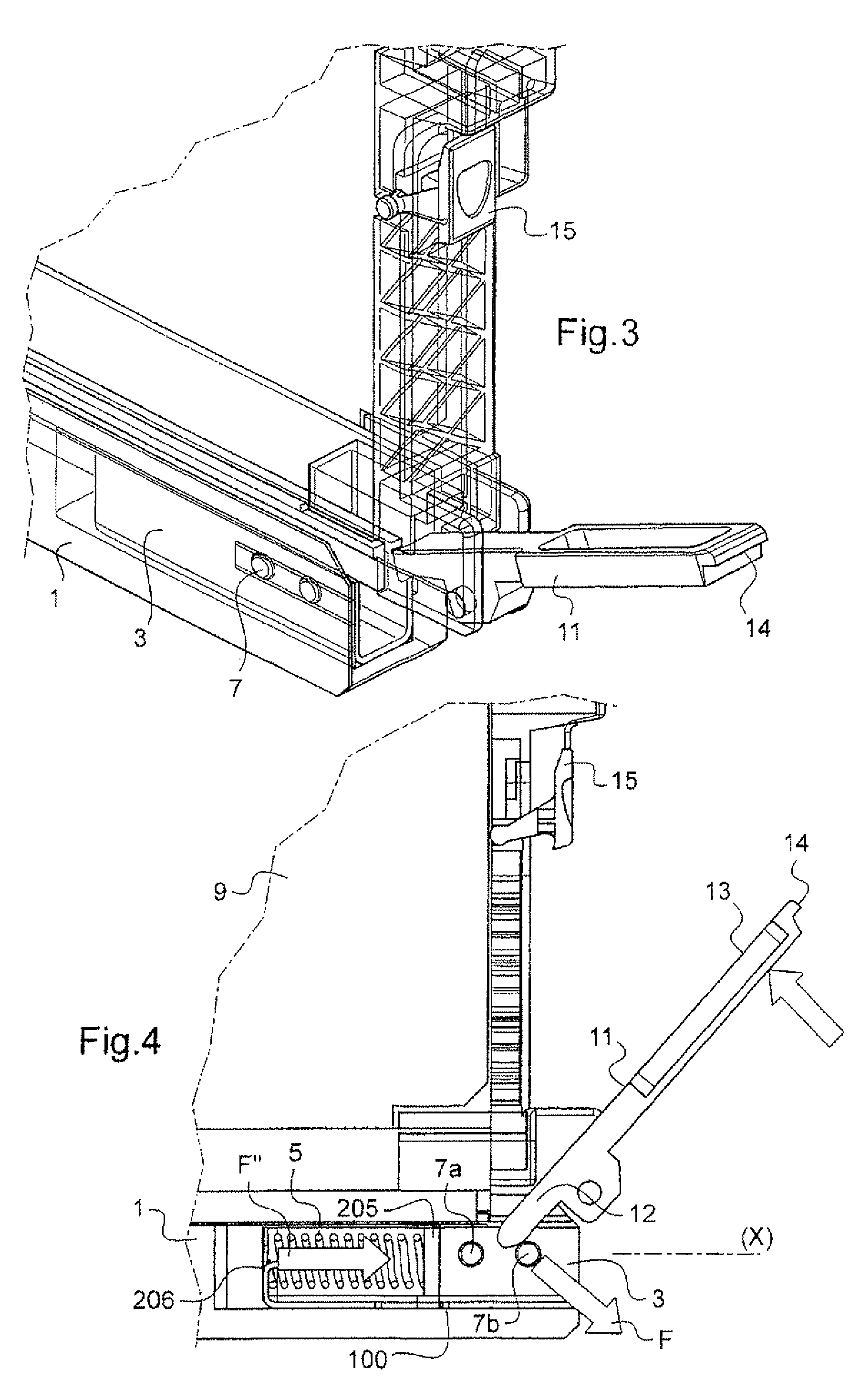
[0091]This assembly comprises a rack given overall reference 1 and an electronics card given overall reference 8.

[0092]FIG. 17 is a diagram of a conventional rack 1. That rack comprises an open front face 200, side cheeks 201, a back plate 202, a top plate 203, and a bottom plate 204. As shown in FIG. 1, a housing 2 is formed inside the bottom plate 204 of the rack 1. A carriage 3 extending along a longitudinal axis X is received in the housing 2 so as to be movable in the housing along the axis X. By way of example, the carriage 3 is made of plastics material or of metal, e.g. being obtained by molding, machining, or cutting and folding.

[0093]In the example described the housing 2 is formed in the bottom plate of the rack close to the entry zone for an electronics card into the rack 1, however the invention is not limited to such an example.

[0094]The carriage 3 has a front portion 4 defining ...


PUM


Abstract

A locking assembly for locking at least one electronics card to a rack, the assembly comprising:at least one electronics card;a rack having a bottom plate with at least one housing; anda locking system for locking the card on the rack;the locking system including at least one resilient prestress element for prestressing the electronics card when it is fastened to the rack.

Description

FIELD OF THE INVENTION[0001]The present invention relates to a system for positioning and locking an electronics card in a rack.[0002]The invention applies more particularly to positioning and locking electronics cards in a rack in the field of aviation, in particular for avionics racks and bays.BACKGROUND OF THE INVENTION[0003]It is known to use daughter electronics cards that are connected at one of their ends to one or more motherboards and / or to isolated connectors that are connected to cabling.[0004]The backplane connections of a rack may for example be made up of one or more connectors, and the positioning and locking of the connection between daughter cards and rack backplane connectors may be performed in various ways.[0005]The rack backplane connector(s) may be fastened rigidly to the rack or may be floatingly mounted transversely and / or axially in order to accommodate positioning defects.[0006]In another known variant, the connectors are mounted floatingly in the axial dir...

Claims


Application Information

Patent Timeline
Patent Type & Authority Patents(United States)
IPC IPC(8): H05K5/00
CPCH05K7/1407H05K7/1409H05K7/1452
Inventor VAN DER MEE, MARNIXALEXANDRE, RENAUDBECAVIN, PATRICE
Owner RADIALL SA
Why Eureka
Try Eureka