A UAV front landing gear compartment based on catapult take-off

A technology of landing gear cabin and nose landing gear, which is applied in the direction of fuselage frame, fuselage bulkhead, aircraft parts, etc. It can solve the problems of torsional load and structural weight increase of the landing cabin section, and achieve the force transmission route and direct, The effect of continuous force and light structure

Active Publication Date: 2021-03-30
CHENGDU AIRCRAFT INDUSTRY GROUP
View PDF6 Cites 0 Cited by
  • Summary
  • Abstract
  • Description
  • Claims
  • Application Information

AI Technical Summary

Problems solved by technology

[0005] In order to overcome the shortcomings of the above-mentioned truss-type large-opening front landing gear cabin, the present invention provides a more secure, reliable and efficient structural layout design scheme, a UAV nose landing gear cabin based on catapult takeoff, which solves the problem In the prior art, the problem of increased structural weight caused by the reinforcement design and the problem of the torsional load of the landing cabin section

Method used


Image

  • A UAV front landing gear compartment based on catapult take-off
  • A UAV front landing gear compartment based on catapult take-off
  • A UAV front landing gear compartment based on catapult take-off

Examples


Embodiment 1

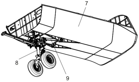
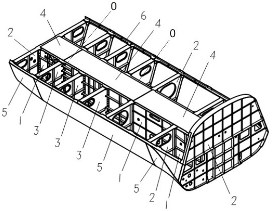
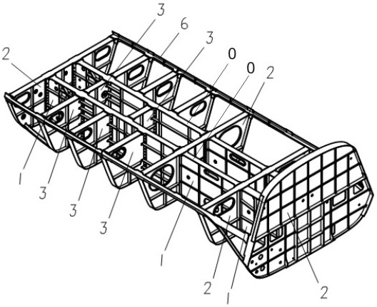
[0029] combined with Figure 1-4 Shown, a kind of unmanned aerial vehicle front landing gear section based on catapult take-off, comprises strip-shaped landing gear compartment and landing gear, and described landing gear compartment comprises bulkhead 2 at two ends and the girder 6 that connects bulkhead 2, and The outer skin 7 is covered; the middle part of the landing gear cabin is provided with a landing gear fixing cabin, and the skeleton of the landing gear fixing cabin includes four main beams 0, and the main beams 0 are fixedly connected with the partition frame 2, Both sides of the main beam 0 and the bulkhead 2 are provided with partitions 3; the main beam 0 and the partition 3 form an integral wall beam 1, and the wall beam 1 is hinged with a landing gear The main pillar 8 and the landing gear slant strut 9, and the skin 7 at the lower part of the fixed compartment of the landing gear is provided with an opening suitable for the landing gear.

[0030] Implementatio...

Embodiment 2

[0035] On the basis of Embodiment 1, further, a plurality of bulkheads 2 are provided between the wall plate beam 1 and the girder 6, and the bulkheads 2 outside the fixed compartment of the landing gear are provided with bulkheads. plate 3.

[0036] Implementation principle:

[0037]The transverse member formed by the bulkhead 2 and the bulkhead 3 in the middle divides the enclosed box body of the landing gear cabin into several, and the transverse member provides transverse support to the longitudinal wall beam 1 and improves the opening The overall rigidity of the box body and the closed box body increases the ability to bear torque, and at the same time disperses the concentrated force transmitted from the wall plate beam 1, and disperses and transmits the concentrated force of the instantaneous impact and large overload, which increases the overall strength of the present invention. For strength and stiffness, the cross members are framed thin plates without adding too m...

Embodiment 3

[0040] On the basis of Embodiment 1 or 2, further, the upper surface of the landing gear compartment is the floor 4 fixed on the bulkhead 2 , the main beam 0 and the main beam 6 .

[0041] Implementation principle:

[0042] By setting the upper surface of the landing gear cabin as the floor 4 that is airtightly connected with the skin, the landing gear cabin becomes a thin-walled semi-monocoque structure. After the floor 4 is set, the load-carrying capacity of the upper part is strengthened.


PUM


Abstract

The invention discloses a drone noselanding gear well section based on catapult-assisted take-off. A landing gear well comprises partition frames at the two ends, a girder connected with the partitionframes and a skin; a landing gear fixing compartment is arranged in the middle of the landing gear well, a framework of the landing gear fixing compartment comprises four main girders, the main girders are fixedly connected with the partition frames, and partition plates are arranged at both the two sides of each main girder and the partition frames; the main girders and the partition plates forman integrated wall plate girder, the wall plate girder is hinged to a landing gear main support and a landing gear slant supporting rod, and openings are formed in the skin at the lower portion of the landing gear fixing compartment. The landing gear well is of a box body type structure low in structural weight, the openings are formed among the main girders, the rigidity of other parts of the landing gear well and the rigidity of an overall aircraft cannot be lowered, and additional strength reinforcement setting is also not needed; the wall plate girder penetrating through the whole box body has the advantages of being continuous in stress and short and direct in force transmitting path, and transmitting of instantaneous impact large loading concentrated force and torque inside the structure is benefited.

Description

technical field [0001] The invention relates to the field of unmanned aerial vehicle landing gear compartment, in particular, it is a front landing gear compartment section of unmanned aerial vehicle based on catapult take-off. Background technique [0002] At present, except for the American X-47B, large and medium-sized UAVs rarely use the catapult take-off method. The common front landing gear compartment of UAVs is generally a truss-type large-opening structure. The front landing gear cabin section of this kind of structural form has the following disadvantages: [0003] 1) The large opening of the nose landing gear compartment weakens the local and overall strength and rigidity of the aircraft, and the reinforcement design of the opening increases the structural weight; [0004] 2) The large opening of the nose landing gear compartment is not conducive to bearing the torsional load. Contents of the invention [0005] In order to overcome the shortcomings of the abov...

Claims


Application Information

Patent Timeline
Patent Type & Authority Patents(China)
IPC IPC(8): B64C1/06B64C1/12
CPCB64C1/061B64C1/064B64C1/12
Inventor 刘忠党万腾何敏刘晓明方雄唐克兵
Owner CHENGDU AIRCRAFT INDUSTRY GROUP
Why Eureka
Try Eureka