Image guided radiation therapy

a radiation therapy and image technology, applied in radiation therapy, radiation therapy, sensors, etc., can solve the problems of low accuracy and achieve the effects of improving accuracy, reducing treatment number, and increasing doses

Active Publication Date: 2012-10-23
DEERFIELD IMAGING INC
View PDF6 Cites 5 Cited by
  • Summary
  • Abstract
  • Description
  • Claims
  • Application Information

AI Technical Summary

Benefits of technology

[0021]It is one object of the invention to provide an improved method and apparatus for radiation treatment which allows an increased accuracy with the possibility of higher doses and lower numbers of treatments while avoiding damaging healthy tissue.

Problems solved by technology

This system is widely used and has been found to have a relatively low accuracy which can often be as poor as 2 cms so that the treatment has to follow a very conservative course to avoid radiation to healthy tissue.

Method used


Image

  • Image guided radiation therapy
  • Image guided radiation therapy
  • Image guided radiation therapy

Examples


Embodiment Construction

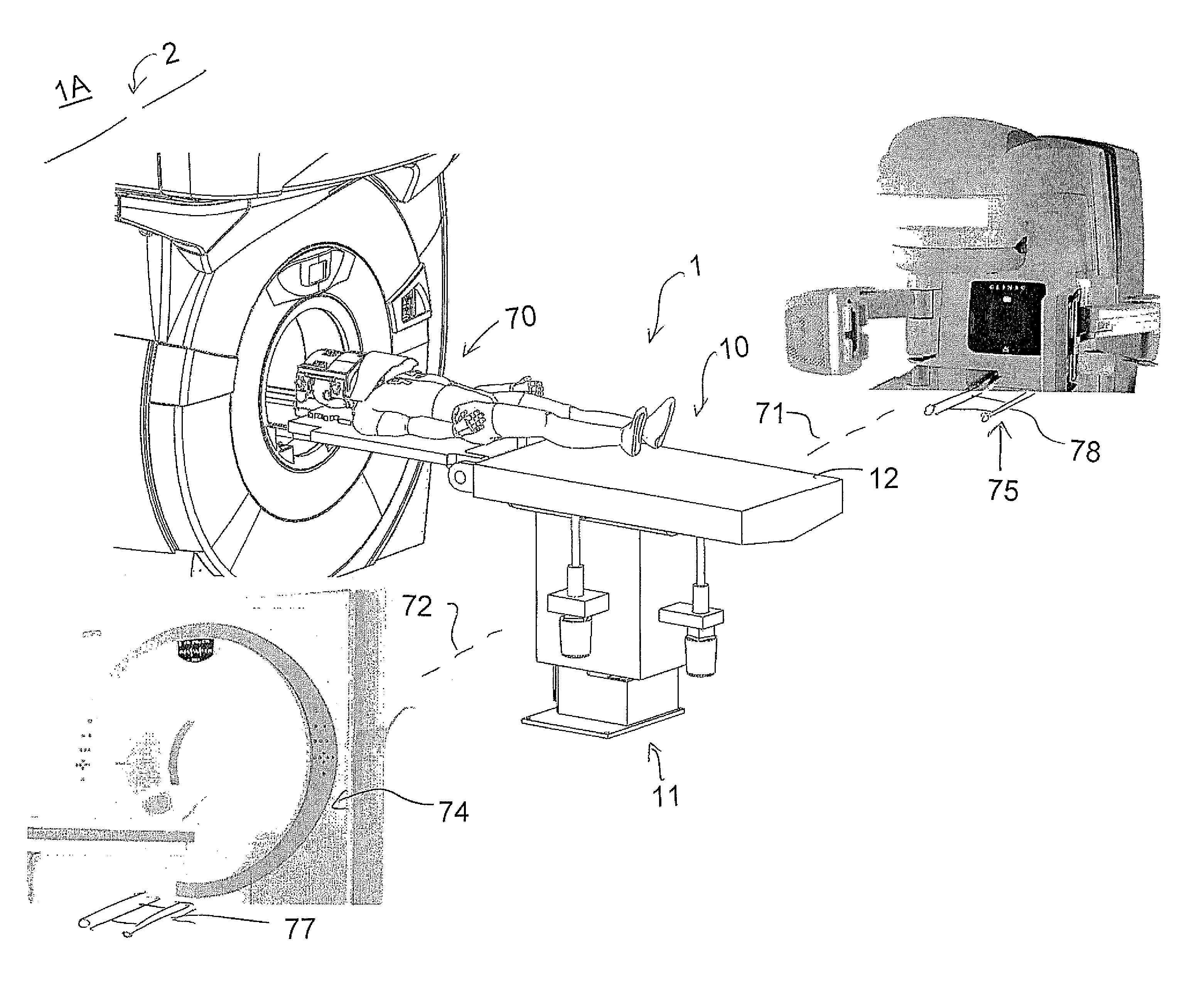
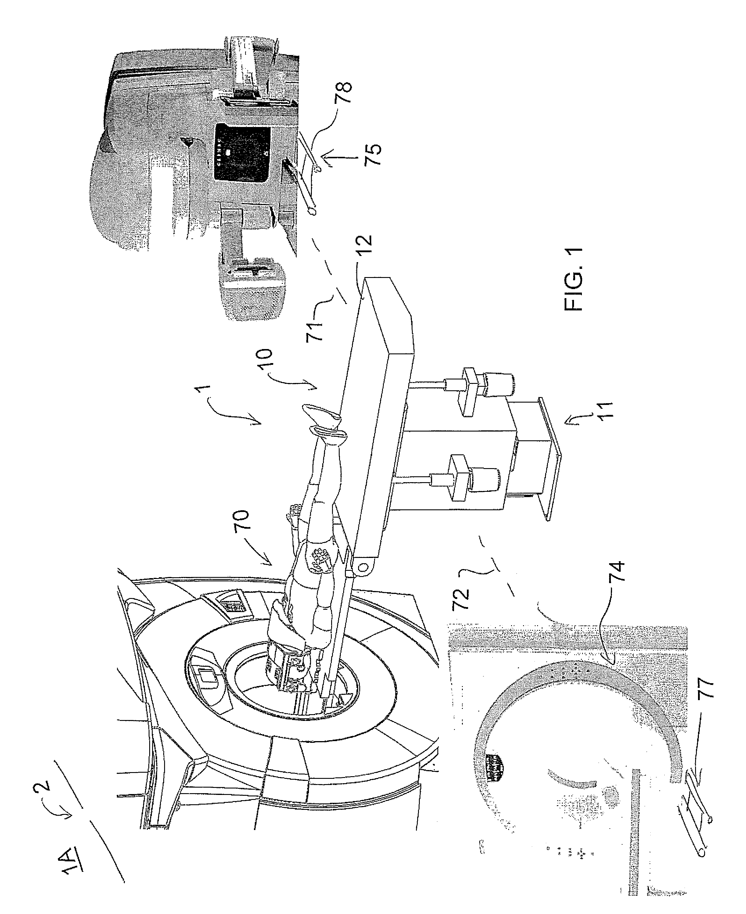
[0104]In FIG. 1 is shown an arrangement for carrying out Magnetic Resonance Imaging of a patient while the patient remains stationary on a patient support table. The arrangement provides a room 1 in which is mounted a patient support table 10 with doors 2 at one side of the room for entry into the room of the magnet 3 of an MR imaging system from a magnet bay 1A.

[0105]The MR imaging system is a high-field (e.g. 1.5 T or 3 T) magnet that moves on overhead rails between the two or more rooms.

[0106]The Patient Handling System or support table is shown in FIG. 1 is indicated generally at 10. The patient support table includes a base or pedestal 11 which allows the base to move a patient support portion 12 to required locations in height and in orientation. At the top of the base 11 is mounted the patient support portion 12 in the form of a generally planar body 12A formed of a fiber reinforced plastics material so as to define a surface area sufficient for supporting the patient while l...


PUM


Abstract

Radiation therapy of a lesion in a part of a patient is carried out by maintaining the patient on a patient support table in fixed position using an immobilization device while the table is rotated between a magnetic resonance imaging system, a CT imaging system for generating a 360 degree scanned image of the patient at the location of the lesion and the radiation therapy system for generating a beam of radiation for treatment of the lesion and for scanning the beam 360 degrees around the lesion. The MR image locates the lesion and the CT system is used to calculate the treatment. Registration between the MR image, the CT image and the radiation treatment is provided by the fixed position of the part of the patient on the table which is held fixed using an immobilization system suitable for the part concerned which may include a molded head mask where the head is involved.

Description

[0001]This application claims the benefit under 35 U.S.C. 119 of Provisional Application Ser. No. 61 / 221,267 filed Jun. 29, 2009.[0002]This invention relates to a system for use in radiation therapy of a lesion in a part of a patient.BACKGROUND OF THE INVENTION[0003]LINAC radiation therapy systems are well known and widely used for radiation treatment of lesions at various locations in the body of the patient. The LINAC device rotates around the body part and applies a variable intensity of radiation to radiate the lesion as accurately as possible.[0004]Typically it is known that an initial CT scan is carried out to plan the treatment using the attenuation data available from the CT image. The CT imaging is effected at a separate location and it is necessary to register the image of the CT scan with the treatment device to use the attenuation data. For this purpose a head-neck extension board is located on the LINAC's table and on the CT table with the same locking space. Also the p...

Claims


Application Information

Patent Timeline
Patent Type & Authority Patents(United States)
IPC IPC(8): A61B6/00A61N5/10
CPCA61N5/10A61N5/1049A61B6/4417A61B5/055A61B6/03A61N2005/1055A61N2005/1061G01R33/34084G01R33/4808A23V2002/00A61B6/0421A61B6/0487
Inventor ZHU, HAOQINPETROPOULOS, LABROSSHVARTSBERG, ALEXANDER
Owner DEERFIELD IMAGING INC
Why Eureka
Try Eureka