
Printed matter seasoning apparatus and method, and inkjet recording apparatus

a seasoning apparatus and inkjet technology, applied in the direction of pile separation, transportation and packaging, article separation, etc., can solve the problems of deviation in the size and position of images printed respectively on the front surface and the rear surface, significant expansion of paper, and mismatch between the register on the front and rear surface, so as to prevent expansion/contraction and deformation of paper, improve the productivity of printed matter, and shorten the time

Active Publication Date: 2012-10-30
FUJIFILM CORP
View PDF3 Cites 6 Cited by
  • Summary
  • Abstract
  • Description
  • Claims
  • Application Information

AI Technical Summary

Benefits of technology

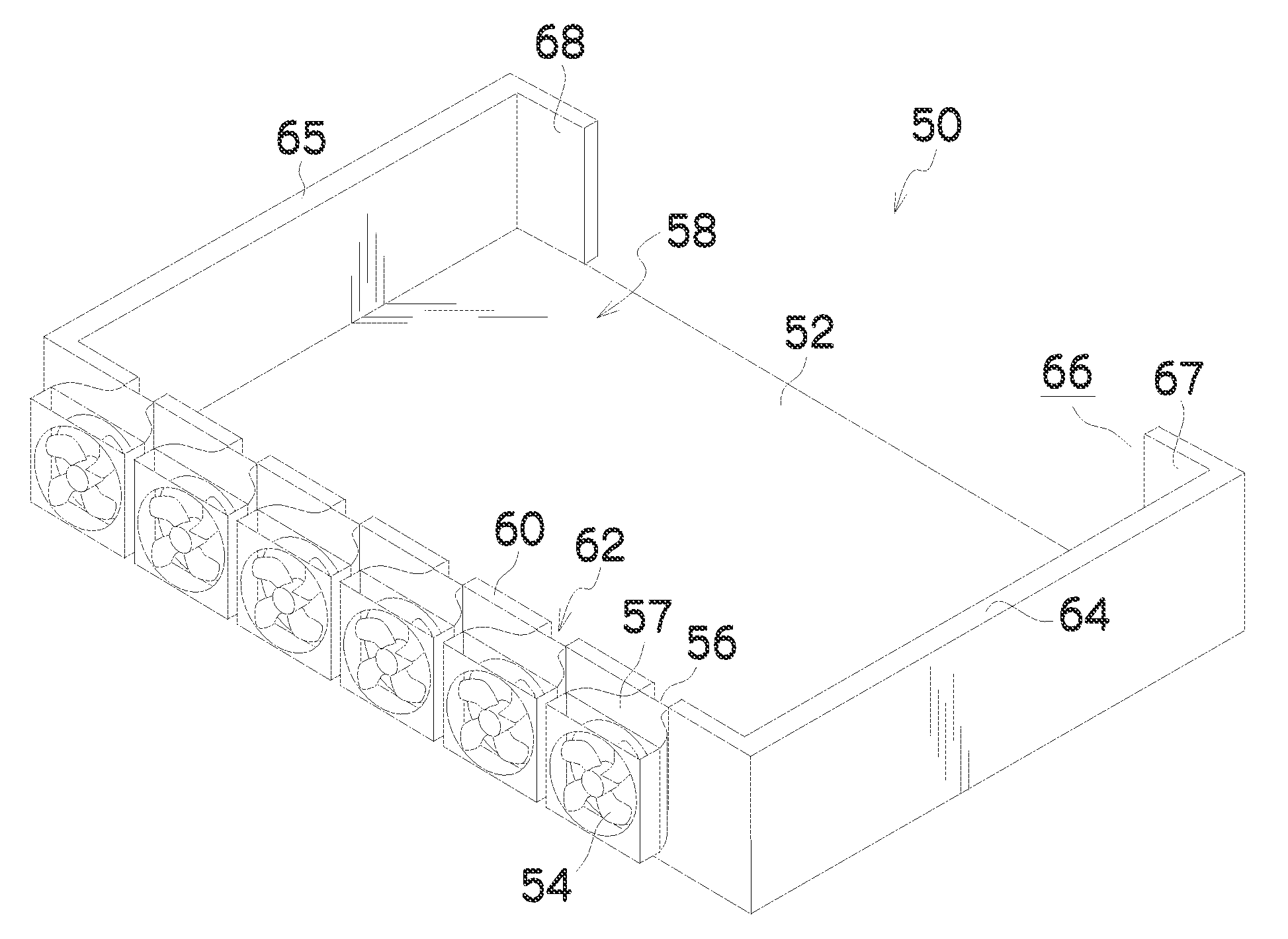
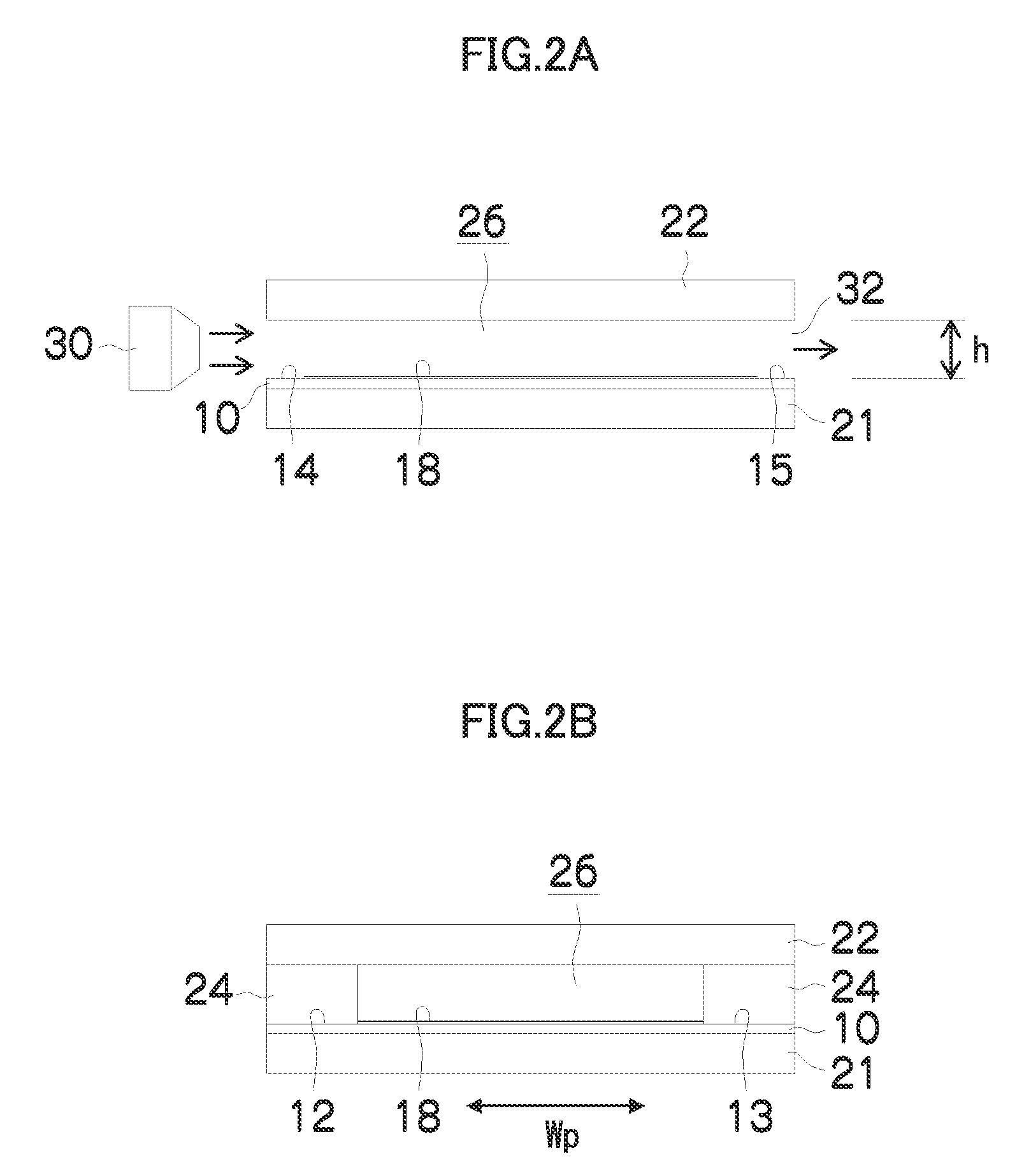
The present invention provides a seasoning apparatus and method for printed matters, as well as an inkjet recording apparatus, that can quickly and uniformly season paper after printing. The apparatus includes a table for placing printed paper, ink having been deposited on at least one surface of each sheet, and an air blowing device that blows air simultaneously between the sheets. The air blowing device can be a ceiling plate member that prevents paper scattering during air blowing. The air blowing device can also have an air blowing port covering the whole area of the paper accommodating section, allowing for simultaneous seasoning of all sheets. The invention aims to provide a faster and more efficient way to season printed paper after printing.

Problems solved by technology

This problem is especially conspicuous in a system which prints onto normal paper using water-based ink Moreover, when carrying out double-side printing, normally, after completing printing on one side (the front surface), printing is carried out on the opposite side (the rear surface); however, immediately after printing on the front surface, there is significant expansion of the paper and a problem arises in that deviation occurs in the size and position of the images printed respectively on the front surface and the rear surface (i.e., there is mismatch in register on the front and rear surfaces).
In the case of single-side printing also, and not only double-side printing, there is a problem of deterioration of printing quality due to the occurrence of curl or cockling as a result of deformation of the paper as described above.
Furthermore, there is also a problem of causing adverse effects on subsequent processing steps, such as a binding process, which are carried out after the printing step.
This technology may have beneficial effects in respect of a single printed sheet; however, if the printing speed is raised and printed matters are stacked in the paper output tray, then it is not possible to obtain a sufficient drying effect.
However, with the air nozzle that moves up and down, the air flow acts intermittently between the paper sheets, and therefore, although satisfactory performance is obtained in respect of the paper separating function, the drying speed is slow.
This composition may have satisfactory performance in terms of sheet separation; however, from the viewpoint of drying, it is difficult to exchange air between the paper sheets due to the closed structure surrounding the paper, and therefore the drying speed is slow.

Method used


Image

  • Printed matter seasoning apparatus and method, and inkjet recording apparatus
  • Printed matter seasoning apparatus and method, and inkjet recording apparatus
  • Printed matter seasoning apparatus and method, and inkjet recording apparatus

Examples


modified embodiment 1

[0116]FIGS. 11 and 12 are schematic drawings showing a seasoning apparatus according to another embodiment of the present invention. FIG. 11 is a plan diagram showing a schematic view of a state during air blowing, and FIG. 12 is a side view of same. In FIGS. 11 and 12, elements which are the same as or similar to the composition described with reference to FIGS. 5 to 9 are denoted with the same reference numerals, and description thereof is omitted here.

[0117]As shown in FIGS. 11 and 12, it is also possible to adopt a mode where an air flow is blown from each of two end sides of the paper 70 stacked on the table 52. In this case, the air passage ports 66 are formed in the side planes where the air blowing units 80 (blowers 54) are not arranged.

[0118]According to this mode, compared to the mode where the air blowing is performed in a single direction, it is possible to reduce the effects of the pressure loss due to the passage of air through the gaps between the paper sheets, and ef...

modified embodiment 2

[0120]FIG. 13 is a schematic drawing showing a seasoning apparatus according to yet another embodiment of the present invention. FIG. 13 is a side view diagram showing a schematic view of a state during air blowing. In FIG. 13, elements which are the same as or similar to the composition described with reference to FIGS. 5 to 9 are denoted with the same reference numerals, and description thereof is omitted here.

[0121]As shown in FIG. 13, it is possible to adopt a composition in which shelf plates 92 are arranged in the paper accommodating section on the table 52, and the sheets of paper 70 are stacked on a plurality of decks separately. FIG. 13 shows an example in which the paper accommodating section is divided into four decks by three shelf plates 92, and the number of shelf plates 92 can be suitably set to one or more, in accordance with the number of decks to be divided. By arranging n shelf plates 92 between the table 52 and the ceiling plate 76, a paper accommodating section ...


PUM

PropertyMeasurementUnit
static pressureaaaaaaaaaa
sizeaaaaaaaaaa
static pressureaaaaaaaaaa

Abstract

The printed matter seasoning apparatus includes: a table on which a plurality of sheets of printed paper are placed in a stack, ink having been deposited on at least one surface of each sheet of the printed paper; and an air blowing device which blows air toward at least one of end sides of the stack on the table to supply the air simultaneously between the respective sheets in the stack. The air blowing device blows the air at an air flow volume of at least 0.02 m3 / (min·m) per sheet of the printed paper and per unit length of the printed paper in a width direction thereof perpendicular to a direction from the air blowing device to the stack on the table.

Description

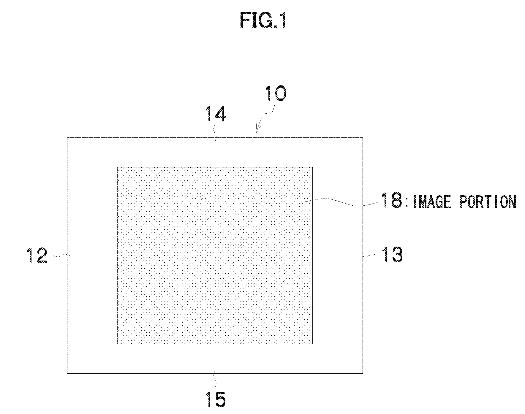
BACKGROUND OF THE INVENTION[0001]1. Field of the Invention[0002]The present invention relates to a printed matter seasoning apparatus and method, and an inkjet recording apparatus, and more particularly, to a seasoning apparatus composition and a seasoning method, and to an inkjet recording apparatus using same, whereby paper after being printed is quickly conditioned close to the ambient temperature and humidity.[0003]2. Description of the Related Art[0004]In a printing system, immediately after ink has been deposited on paper, expansion and contraction of the paper occurs due to the difference in moisture content resulting from the light and dark tones of the ink (i.e., different ink volumes) in the image region. This problem is especially conspicuous in a system which prints onto normal paper using water-based ink Moreover, when carrying out double-side printing, normally, after completing printing on one side (the front surface), printing is carried out on the opposite side (the...

Claims


Application Information

Patent Timeline
Patent Type & Authority Patents(United States)
IPC IPC(8): B41J2/01B41J29/38
CPCB41J3/60B41J11/002B41J13/106B65H29/246B65H31/00B65H2801/31B65H2301/517B65H2406/12B65H2407/311B65H2801/12B65H2801/15B65H2301/4212B41J11/0022B41J11/00214B65H2407/30
Inventor CHIWATA, YUHEI
Owner FUJIFILM CORP
Learn More