Clinch pin fastener

a technology of clinch pins and fasteners, which is applied in the direction of threaded fasteners, screwed fasteners, manufacturing tools, etc., can solve the problems of additional cleaning costs of parts, and achieve the effects of reducing secondary formation operations, tight tolerances, and small clinching features

Active Publication Date: 2012-10-30
PEM MANAGEMENT INC
View PDF29 Cites 13 Cited by
  • Summary
  • Abstract
  • Description
  • Claims
  • Application Information

AI Technical Summary

Benefits of technology

[0004]In order to meet the above-described need in the art, the present invention eliminates secondary formation operations of a clinch-type fastener by creating an undercut during the same forging operation that creates the head and the displacer. Other features that are formed in the present fastener at the same time as the undercut are a tapered point and a tangential interference band provided by a curvilinear shaped bulge in the shank. The configuration of these elements according to the present invention are of paramount importance for fastening pins in the range of 1 millimeter in diameter because very small clinching features require a very tight tolerance to be held for the displacer diameter and height as well as the undercut diameter and shank diameters. The present clinching pin described herein includes a tangential interference band and a tapered point which work together to guide the part through a very small diameter hole in the attached plate while creating a slight interference fit between the hole and the fastener at the interference band diameter only. This creates minimal stresses in the plate while eliminating any tolerance between the inner wall of the hole and the outer diameter of the clinching pin.

Problems solved by technology

When threads are not necessary, the undercut still requires the secondary operation which also incurs the additional cost of cleaning the part.

Method used


Image

  • Clinch pin fastener
  • Clinch pin fastener
  • Clinch pin fastener

Examples


Embodiment Construction

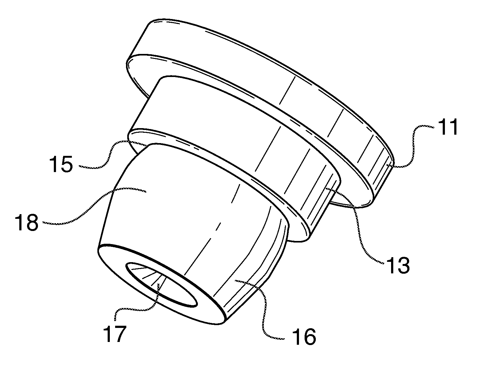
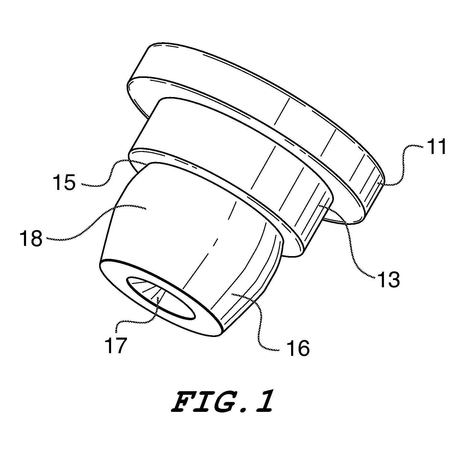
[0013]Referring now to FIG. 1, the present clinching pin is a forged metal part having a head 11, a displacer shoulder 13 and an undercut 15 that receives a cold flow of metal from the plate into which the part is pressed. It further includes a tapered tip 16 and a circumferential interference band 18 along the greatest diameter of its barrel-shaped shank. A recess 17 is present in the bottom end. As will be described further below, all features of this pin are created in one forming operation. Typically, this part is used to hold two sheets of material together. A top panel can be captivated beneath the head of the pin while the body of the pin is clinched into the bottom plate.

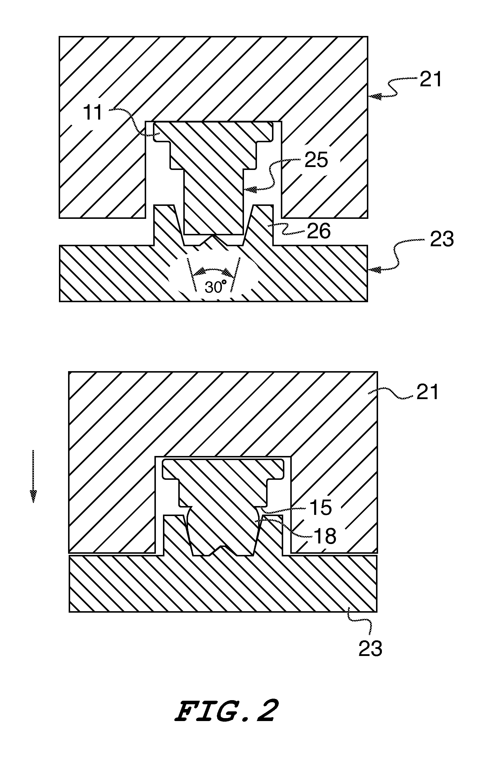
[0014]Referring now to FIG. 2, the present fastener is formed using well known cold forging equipment which includes a top die 21 and a bottom die 23 as shown. The head and displacer are formed first as in any heading operation for the creation of a standard bolt or screw. As shown in this figure, the body o...


PUM

PropertyMeasurementUnit
heightaaaaaaaaaa
surface angleaaaaaaaaaa
included angleaaaaaaaaaa

Abstract

A clinch-type fastener is formed by simultaneously creating an undercut during the same forging that creates the head and displacer of the fastener. A fastener blank is compressed end-to-end between top and bottom dies whereby the axial compression of a blank causes the outward bulging of the shank at its midline. Simultaneously, a tapered end point and a tangential interference band are formed provided by a curvilinear-shaped bulge in the shank. As the bulge is formed an undercut is created between the bulge and a shoulder which extends downwardly from a head of the fastener. This method of formation and the fastener produced thereby are particularly suited to the manufacture of small clinch pins having a diameter in the range of 1.0 mm.

Description

RELATED APPLICATION[0001]This patent application is related to provisional patent application Ser. No. 61 / 254,467 entitled “Clinch Pin Fastener” filed on Oct. 23, 2009, priority from which is hereby claimed.FIELD OF THE INVENTION[0002]The present invention relates to fasteners which attach to metal panels by the cold flow of panel material around the fastener. This type of fastener is generally referred to as a clinch-type fastener.BACKGROUND OF THE INVENTION[0003]Clinching fasteners are retained in the plates into which they are installed by a displacer feature of the fastener which is followed by an undercut directly beneath it. When pressed into a properly sized hole, metal from the edge of the hole is forced by the displacer to flow into the undercut around the circumference of the fastener. When a clinching or clinch-type stud is manufactured, typically a head and displacer are forged into a pin blank. The undercut is then rolled into the part in a secondary operation. Often, a...

Claims


Application Information

Patent Timeline
Patent Type & Authority Patents(United States)
IPC IPC(8): F16B21/00
CPCB21K1/58B21J15/02B21K25/00F16B19/06
Inventor MALONEY, MICHAEL
Owner PEM MANAGEMENT INC
Why Eureka
Try Eureka