Fan

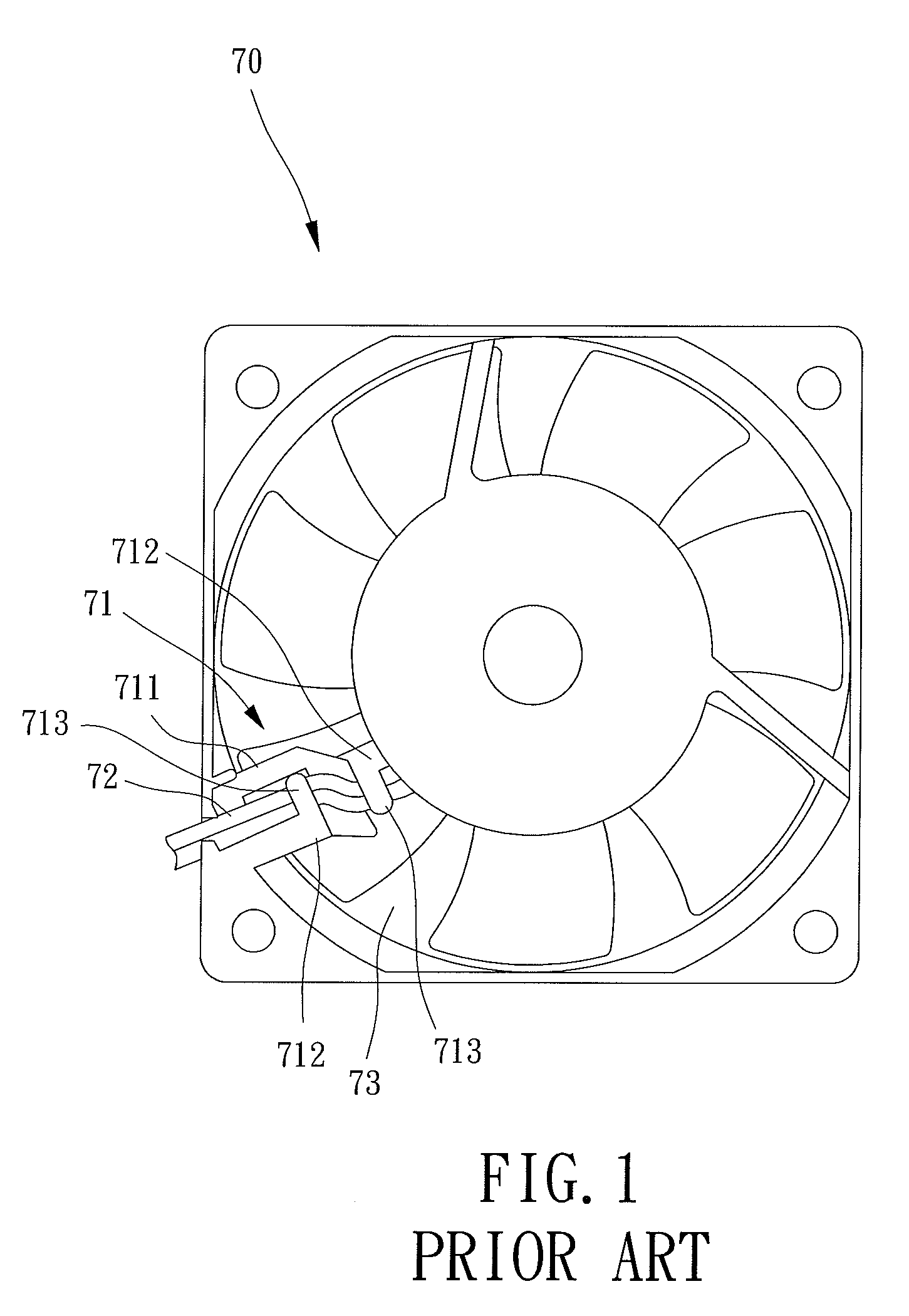
a fan and fan body technology, applied in the field of fans, can solve the problems of increasing the difficulty of assembly of the power line b>72/b>, inconvenient assembly, and increasing the overall cost of the fan

Active Publication Date: 2012-10-30
SUNONWEALTH ELECTRIC MACHINE IND
View PDF23 Cites 8 Cited by
  • Summary
  • Abstract
  • Description
  • Claims
  • Application Information

AI Technical Summary

Benefits of technology

[0007]An objective of the present invention is to provide a fan with ribs, which avoids difficulties and inconvenience in the assembly of the power line.
[0009]A fan according to the preferred teachings of the present invention includes a housing having a peripheral wall defining a compartment. A shaft seat is provided in the compartment. The peripheral wall includes a wire-guiding slot in communication with the compartment. A plurality of connecting members links the shaft seat and the peripheral wall. One of the connecting members is taken as a line fixed portion while a linking end is axially aligned with the wire-guiding slot. A base is coupled to the housing. The base includes a coil unit and a connection port electrically connected to the coil unit. A power line is located at the line fixed portion. The power line includes one end connected with the connection port while the other end extends beyond the housing via the wire-guiding slot. An impeller includes a hub, a shaft, and a permanent magnet, with both the shaft and the permanent magnet are mounted to the hub. The shaft is coupled to the shaft seat, and the permanent magnet having a magnet face faces the coil unit. Thus, the line fixed portion can be as close to the wire-guiding slot as possible. As a result, the power line can extend straight beyond the housing from the connection port, and the circuitous extension of the power line inside the housing for reaching the wire-guiding slot is needless, so that assembling convenience can be enhanced.
[0011]In preferred forms, the connection port of the base is located outside of a radially rotational area of the permanent magnet, and the connection port is intermediate an outer periphery of the permanent magnet and an inner peripheral face of the peripheral wall of the housing. Thus, a spacing between the permanent magnet and the base can be shortened, since the connection port and the power line are not located in the spacing. Thus, the axial height of the fan can be reduced.
[0012]In preferred forms, the line fixed portion with a linking end is located on a straight reference line passing through the shaft seat and the wire-guiding slot. An extension is formed at an outer periphery of the base. The extension extends radially outward from the outer periphery of the base towards the wire-guiding slot. The connection port is formed on a surface of the extension. Thereby, the connection port can be closer to the wire-guiding slot so that the power line can extend through the wire-guiding slot easily. Thus, assembling convenience of the power line can be further enhanced.
[0016]In preferred forms, the housing includes a bottom wall formed inside the peripheral wall and defining the compartment. A plurality of catches is formed on the bottom wall and located in the compartment. The base is mounted in the compartment and abuts the bottom wall. The catches engage with an outer periphery of the base to enhance coupling ability of the base with the housing.

Problems solved by technology

However, the power line still needs a very complicate winding method leading to inconvenience in assembly.
However, the difficulty of assembly of the power line 72 is increased.
Furthermore, the wire-positioning mechanism 71 is complex and, thus, increases the overall costs of the fan 70.

Method used


Image

  • Fan
  • Fan
  • Fan

Examples


first embodiment

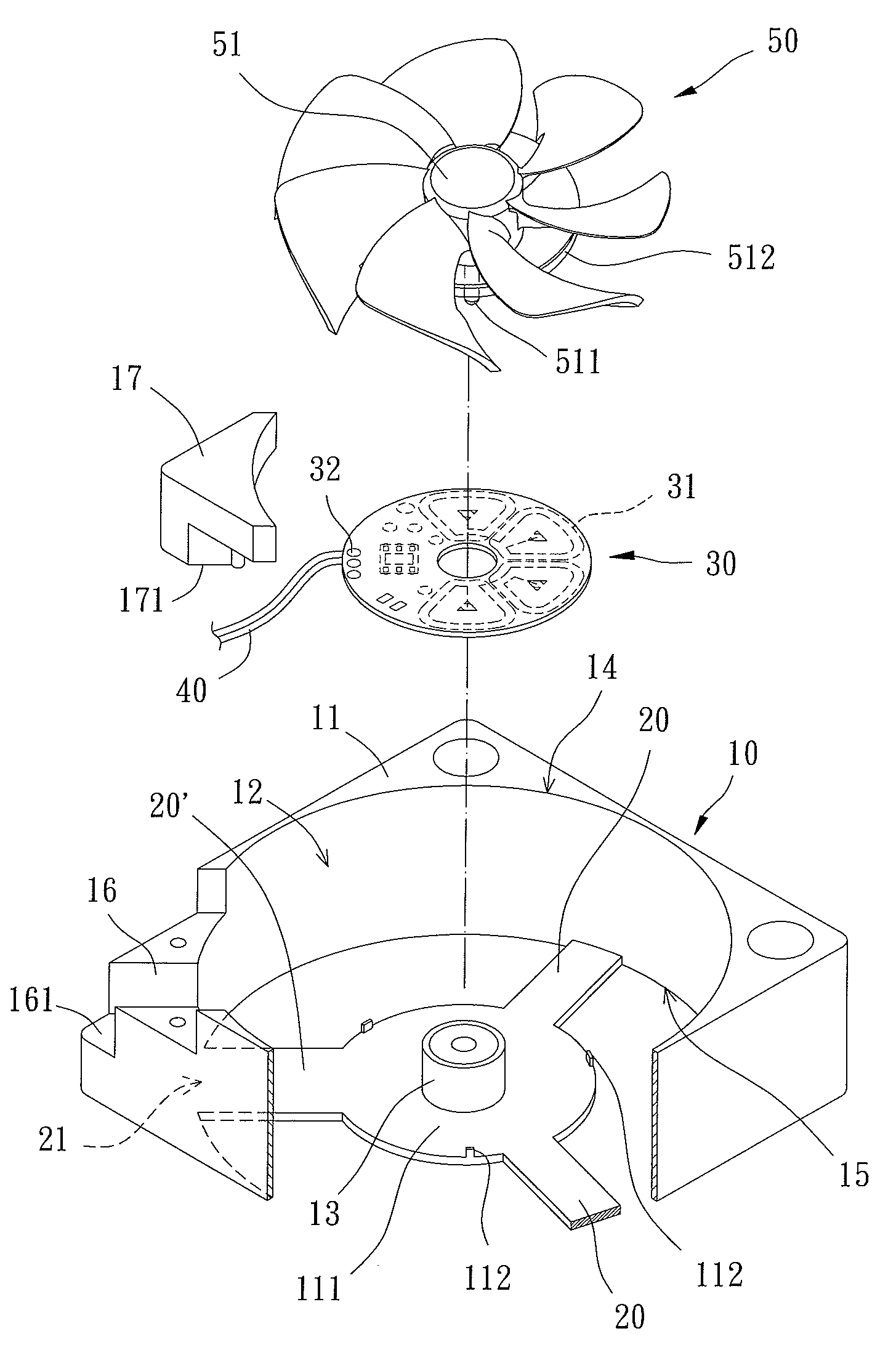
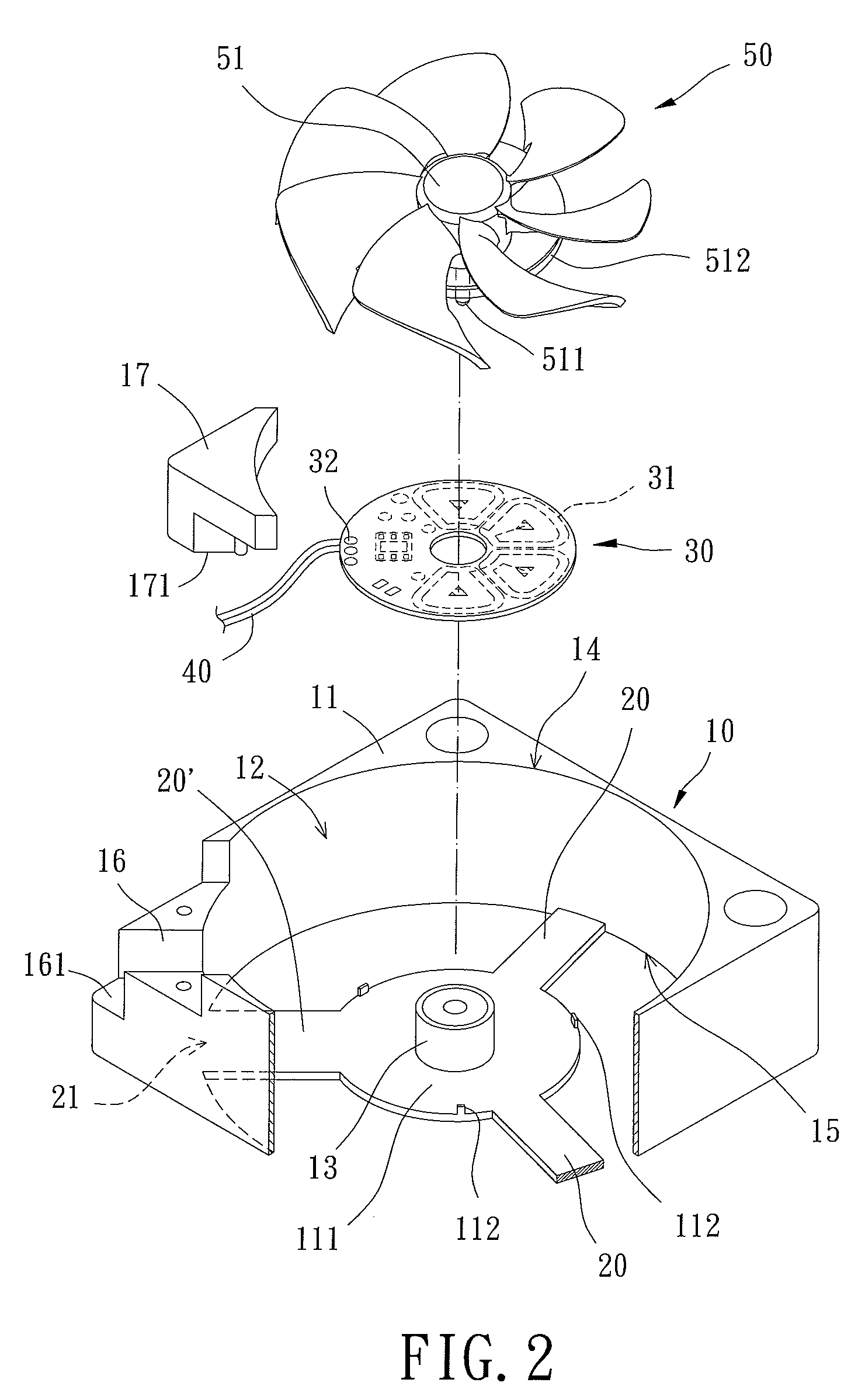
[0031]A fan of a first embodiment according to the preferred teachings of the present invention is shown in FIGS. 2 and 3. The fan includes a housing 10, a plurality of connecting members 20, a base 30, a power line 40, and an impeller 50. The housing 10 includes a peripheral wall 11 defining a compartment 12. A shaft seat 13 is provided in the compartment 12. The housing 10 further includes an air inlet 14 and an air outlet 15 both in communication with the compartment 12. The peripheral wall 11 includes a wire-guiding slot 16 in communication with the compartment 12. Preferably, the wire-guiding slot 16 is located in a corner of the peripheral wall 11 of the housing 10. The housing 10 further includes a bottom wall 111 formed inside the peripheral wall 11 and defining the compartment 12. A plurality of catches 112 is formed on the bottom wall 111 located in the compartment 12. Besides, the shaft seat 13 is preferably mounted on the bottom wall 111 and located between the catches 1...

second embodiment

[0041]FIGS. 5 and 6 show a base 30a of a fan of a second embodiment according to the preferred teachings of the present invention. The connection port 32 of the base 30a is located outside of a radially rotational area of the permanent magnet 512. That is, a distance between the shaft 511 and the connection port 32 is larger than that between the shaft 511 and an outer circumference of the permanent magnet 512. Specifically, the connection port 32 is radially between an outer periphery of the permanent magnet 512 and an inner peripheral face of the peripheral wall 11 of the housing 10. Furthermore, a spacing D (FIG. 7) between the permanent magnet 512 of the impeller 50 and the base 30a can be shortened, since the connection port 32 and the power line 40 are not located in the spacing D. Thus, the overall axial height of the fan along the axis can be reduced.

third embodiment

[0042]FIGS. 8 and 9 show a base 30b of a fan of a third embodiment according to the preferred teachings of the present invention. The linking end 21 of the line fixed portion 20′ is preferably located on the reference line L. According to the position of the line fixed portion 20′, an extension 33 is formed at an outer periphery of the base 30b, with the extension 33 extending toward the wire-guiding slot 16 of the housing 10 and also located on the reference line L. Moreover, the extension 33 can be coupled to the line fixed portion 20′, and the connection port 32 is formed on a face of the extension 33. Furthermore, by providing the extension 33 of the base 30b, the connection port 32 of the base 30b is located outside of the radially rotational area of the permanent magnet 512 of the impeller 50. Further, the connection port 32 is closer to the wire-guiding slot 16, so that straight insertion of the power line 40 through the wire-guiding slot 16 is easier, further enhancing the a...


PUM


Abstract

A fan has a housing with a wire-guiding slot. One of plural connecting members is taken as a line fixed portion having a linking end facing the wire-guiding slot, with the linking end connecting to a section of a peripheral wall of the housing and the section axially aligned with the wire-guiding slot of the housing. A base is coupled to the housing. A power line has one end connected with the connection port and the other end extended beyond the housing via the wire-guiding slot. An impeller is rotatably mounted inside of the housing. Therefore, the line fixed portion can be close to the wire-guiding slot. Thus, the power line can be extended straight through the wire-guiding slot. A distance between the connection port and the wire-guiding slot is shortened to enhance assembling convenience of the power line.

Description

BACKGROUND OF THE INVENTION[0001]1. Field of the Invention[0002]The present invention relates to a fan and, more particularly, to a fan allowing easy assembly of a power line and including ribs or stationary blades.[0003]2. Description of the Related Art[0004]Conventional fans generally include a power line. The position for fixing the power line must be carefully arranged to avoid the power line from being loosened or being entangled in an impeller of the currently available fan. Moreover, conventional fans can be distinguished into two types. The first type of conventional fans doesn't have a design of a rib or stationary blade. The second type of conventional fans includes a rib or stationary blade. The power line arranging methods for these two types of conventional fans are different.[0005]For example, the first type of heat-dissipating fans is disclosed in Taiwan Patent Publication No. 449682 and Taiwan Patent Publication No. 443435. A channel is formed on a housing so that th...

Claims


Application Information

Patent Timeline
Patent Type & Authority Patents(United States)
IPC IPC(8): F04D25/06
CPCF04D25/0653F04D25/0693
Inventor HORNG, ALEX
Owner SUNONWEALTH ELECTRIC MACHINE IND
Why Eureka
Try Eureka