Boom mooring system

a mooring system and boom technology, applied in special-purpose vessels, water cleaning, transportation and packaging, etc., can solve the problems of ineffective anchoring of containment booms and minimal weight of anchoring systems, and achieve the effect of evenly dispersing stresses

Inactive Publication Date: 2012-11-06
LARA KIM A
View PDF12 Cites 4 Cited by
  • Summary
  • Abstract
  • Description
  • Claims
  • Application Information

AI Technical Summary

Benefits of technology

[0009]A system for efficiently anchoring containment booms over extended periods of time and in varying sea conditions. The invention generally relates to a containment boom which includes a buoy having a frame, a buoyancy member mounted on the frame, connecting plates located on first and second ends of the frame for connecting containment booms to the frame, and an anchor secured to the frame for mooring the buoy. The interconnecting frame will help to evenly distribute stresses caused from securely anchoring the containment boom in a dynamic sea environment. The anchor may be secured to the frame in various manners, such as a pipe movably extending through the frame or an elongated member, such as a rope, cable, etc. secured to the frame or pin of the frame. The buoyancy member may include a protective coating thereon. Various signaling devices may also extend from the buoy, such as lights, flags, etc. to designate presence of the buoys and containment boom and / or to designate openings in the containment boom to allow passage of spill response vessels.

Problems solved by technology

One problem with existing anchoring systems is that because the anchoring system is affixed to the underside of the containment boom, the weight of the anchoring system must be minimal to avoid ripping or tearing the containment boom, as well as to allow movement of the containment boom through the water body.
Because of the lightweight anchoring system, the containment booms often times cannot be efficiently anchored during rough sea conditions.

Method used


Image

  • Boom mooring system
  • Boom mooring system
  • Boom mooring system

Examples


Embodiment Construction

A. Overview

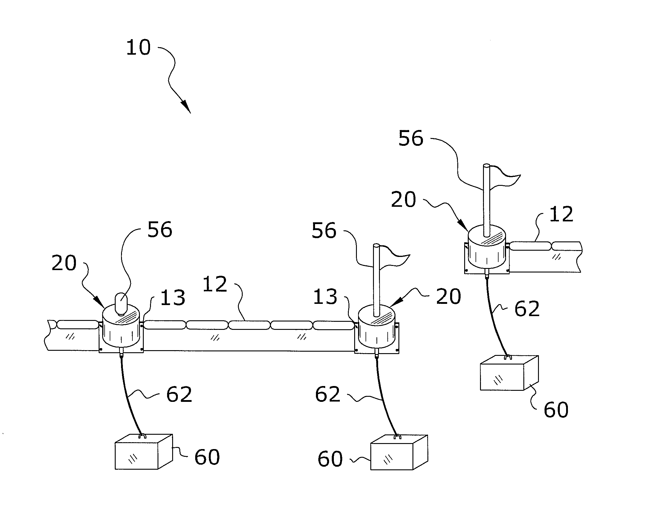
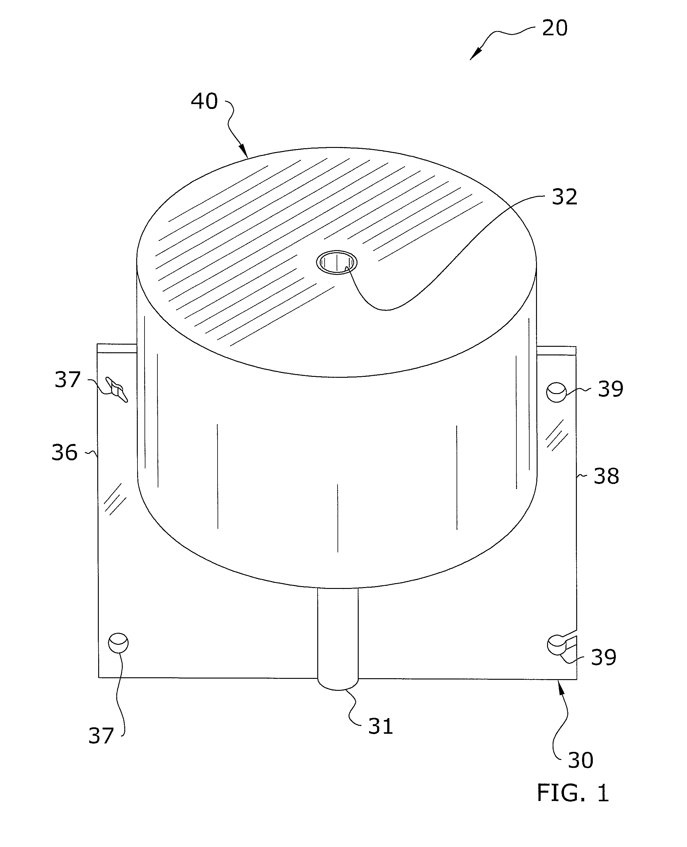
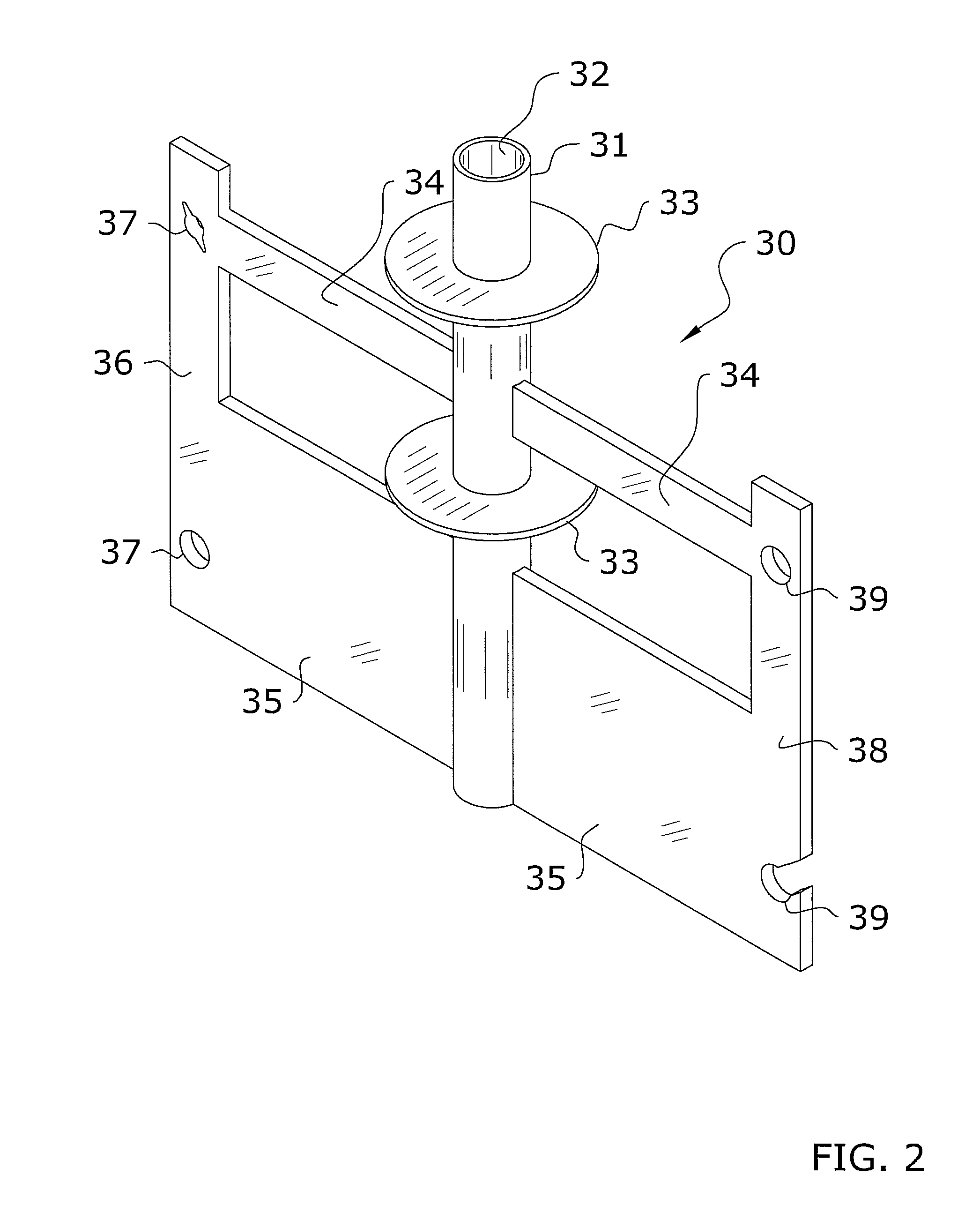
[0021]Turning now descriptively to the drawings, in which similar reference characters denote similar elements throughout the several views, FIGS. 1 through 9 illustrate a boom mooring system 10, which comprises a buoy 20 having a frame 30, a buoyancy member 40 mounted on the frame 30, connecting plates 36, 38 located on first and second ends of the frame 30 for connecting containment booms 12 to the frame 30, and an anchor 60 secured to the frame 30 for mooring the buoy 20. The anchor 60 may be secured to the frame 30 in various manners, such as a pipe 64 movably extending through the frame 30 or an elongated member 62, such as a rope, cable, etc. secured to the frame 30 or pin 50 of the frame 30.

[0022]The buoyancy member 40 may include a protective coating 44 thereon. Various signaling devices may also extend from the buoy 20, such as lights, flags, etc. to designate presence of the buoys 20 and containment boom 12 and / or to designate openings in the containment boom 12...


PUM


Abstract

A boom mooring system for anchoring containment booms over extended periods and in varying sea conditions. The system generally includes a buoy having a frame, a buoyancy member mounted thereto, connecting plates located on first and second ends of the frame for connecting containment booms, and an anchor secured to the frame for mooring the buoy. The frame evenly distributes stresses caused from securely anchoring the containment boom in a dynamic sea environment. The anchor may be secured to the frame in various manners, such as via a pipe movably extending through the frame or an elongated member, such as a rope, cable, etc. secured to the frame or pin of the frame. Various signaling devices may extend from the buoy, such as lights, flags, etc. to designate presence of the buoys and containment boom and / or to designate openings in the containment boom to allow passage of spill response vessels.

Description

CROSS REFERENCE TO RELATED APPLICATIONS[0001]Not applicable to this application.STATEMENT REGARDING FEDERALLY SPONSORED RESEARCH OR DEVELOPMENT[0002]Not applicable to this application.BACKGROUND OF THE INVENTION[0003]1. Field of the Invention[0004]The present invention relates generally to a containment boom and more specifically it relates to a boom mooring system for efficiently anchoring containment booms over extended periods of time and in varying sea conditions.[0005]2. Description of the Related Art[0006]Any discussion of the related art throughout the specification should in no way be considered as an admission that such related art is widely known or forms part of common general knowledge in the field.[0007]Containment booms have been in use for years and are typically utilized to contain leaked or spilled contaminants or substances, such as oil, within water bodies. The containment booms are generally comprised of elongated sections adapted to float in the water in a semi-...

Claims


Application Information

Patent Timeline
Patent Type & Authority Patents(United States)
IPC IPC(8): E02B15/04
CPCB63B22/04B63B22/24E02B15/0807
Inventor LARA, KIM A.
Owner LARA KIM A
Why Eureka
Try Eureka