Automatic speed reduction ratio switching apparatus

a technology of automatic speed reduction and switching apparatus, which is applied in mechanical devices, gearing details, gearing, etc., can solve the problems of grease leakage, variation in torque characteristics of electric actuators, etc., and achieve the effect of reliably obtaining a fixed torque characteristi

Active Publication Date: 2012-11-06
SMC CORP
View PDF2 Cites 53 Cited by
  • Summary
  • Abstract
  • Description
  • Claims
  • Application Information

AI Technical Summary

Benefits of technology

[0009]In view of the above problems, the present invention has an object to provide an automatic speed reduction ratio switching apparatus that is not influenced by temperature changes or the like, and which is capable of reliably obtaining a fixed (fixed quantitative) torque characteristic by means of a simple mechanical structure.
[0012]In accordance with the present invention, the slide resistance member is arranged between the internal gear and the carrier, such that when the thrust force is applied at or above the predetermined value, displacement of the internal gear in the axial directions is made possible. Owing thereto, compared to a structure that uses a viscous resistance medium, fluctuations in the resistance value due to changes in temperature, and leakage of the viscous resistance medium, do not occur, so that under normal operation, a fixed quantitative torque characteristic can be maintained. Consequently, automatic switching of the speed reduction ratio can be effected with high precision by means of a simple mechanical structure.

Problems solved by technology

However, since grease, for example, is used to provide the viscous resistance, the viscosity (resistance value) of the grease tends to vary due to changes in temperature, and there is also concern that leakage of the grease may be brought about.
Thus, a problem exists in that torque characteristics of the electric actuator are subject to variation.

Method used


Image

  • Automatic speed reduction ratio switching apparatus
  • Automatic speed reduction ratio switching apparatus
  • Automatic speed reduction ratio switching apparatus

Examples


Embodiment Construction

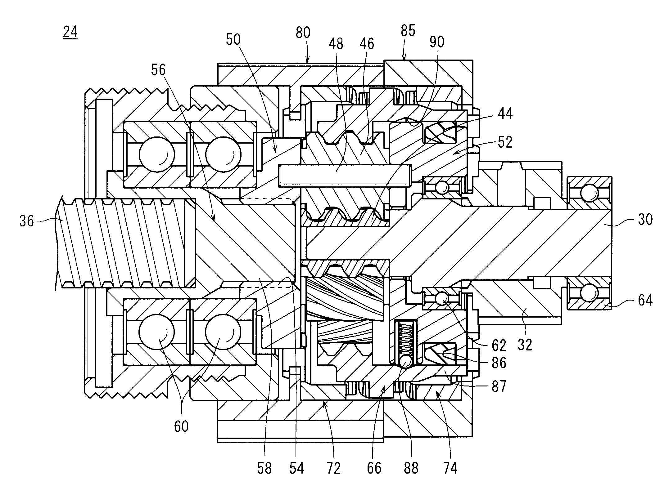
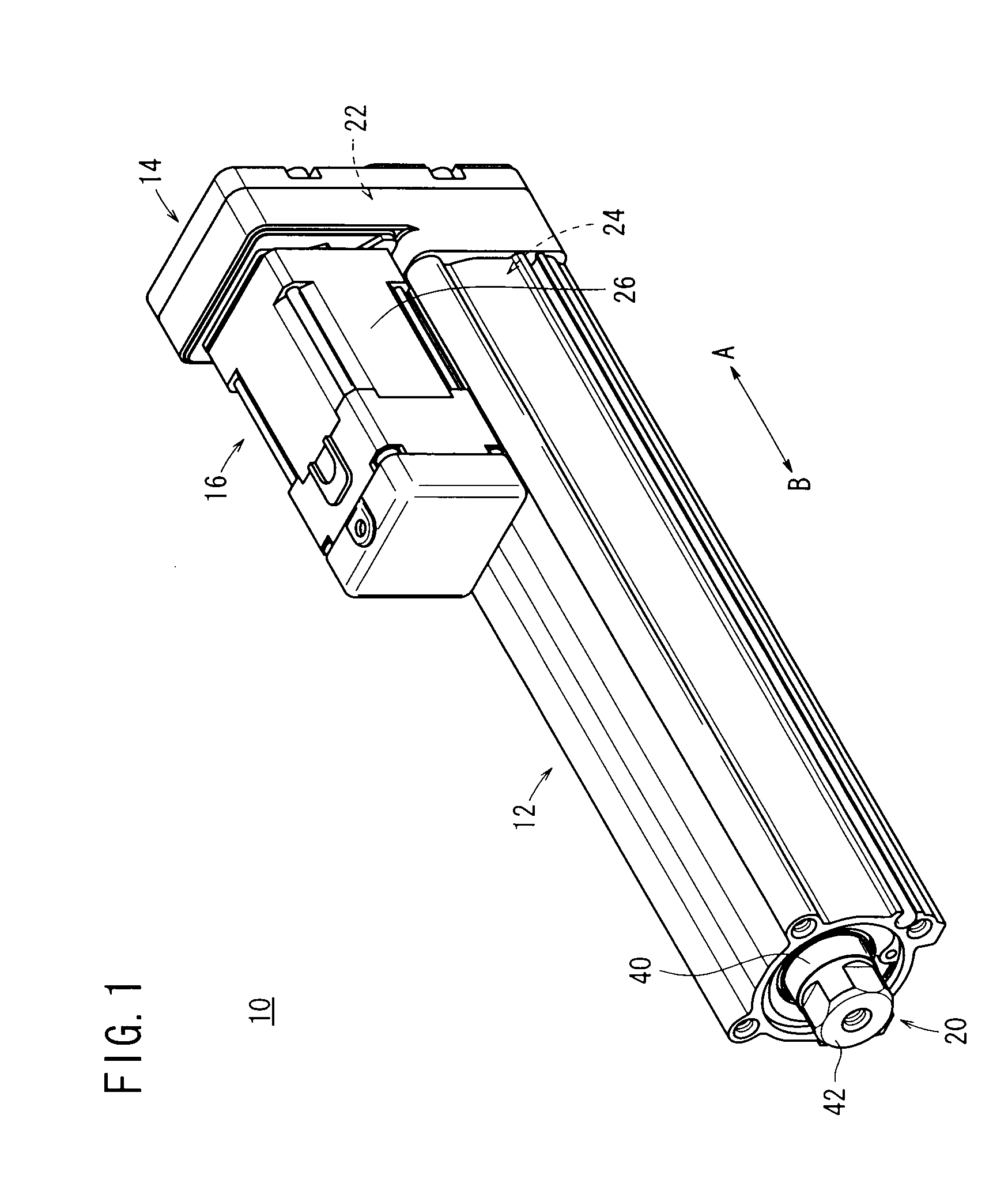
[0021]FIG. 1 is an exterior perspective view of an electric actuator 10 in which an automatic speed reduction ratio switching apparatus 24 according to an embodiment of the present invention is incorporated. The automatic speed reduction ratio switching apparatus 24 is not restricted to use in an electric actuator as described below, but is capable of being used in various other types of equipment.

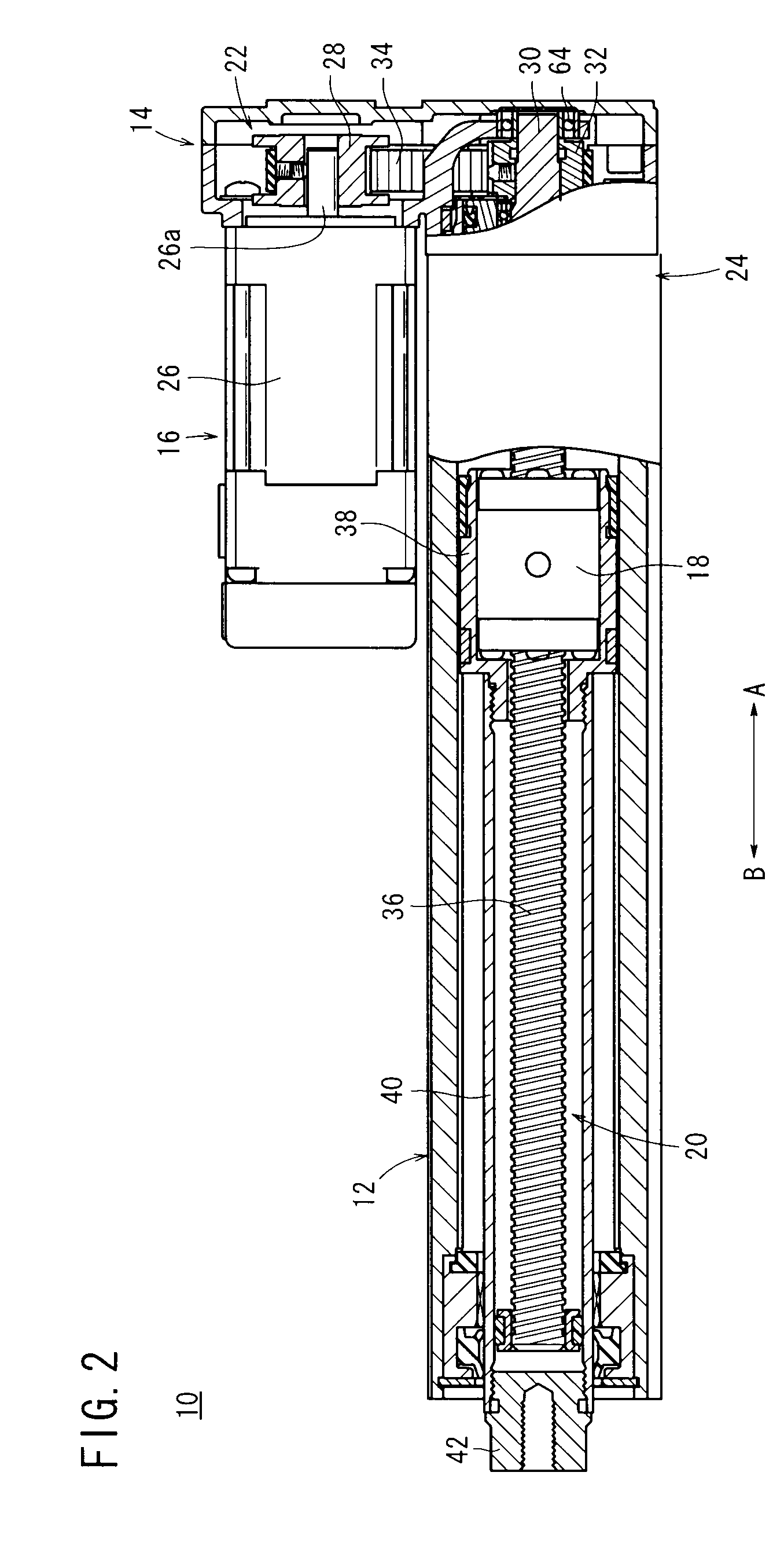
[0022]As shown in FIGS. 1 and 2, the electric actuator 10 comprises an elongate body 12 extending in an axial direction (the direction of arrows A and B), a cover unit 14 connected to one end of the body 12, a driving section 16 which is disposed in parallel to the body 12 and rotatably driven by an electric signal, a displacement mechanism 20 provided inside the body 12 and having a displacement nut 18 which is displaceable over a given stroke by a drive force from the driving section 16, a drive force transmission mechanism 22 for transmitting the drive force from the driving section 16 ...


PUM


Abstract

An automatic speed reduction ratio switching apparatus is equipped with a sun gear connected to an input shaft, first and second carriers connected to a feed screw shaft, planetary gears meshed with the sun gear and which are mounted rotatably in the first and second carriers, and an internal gear meshed with the planetary gears and which is capable of movement in an axial direction. A packing member is arranged between the internal gear and the second carrier, for regulating movement in the axial direction of the internal gear, while enabling movement of the internal gear in the axial direction when a thrust force is applied at or above a predetermined value.

Description

BACKGROUND OF THE INVENTION[0001]1. Field of the Invention[0002]The present invention relates to an automatic speed reduction ratio switching apparatus for automatically switching a speed reduction ratio between an input shaft connected to a rotary drive source and an output shaft connected to an actuating member.[0003]2. Description of the Related Art[0004]Heretofore, as a means for transporting workpieces and the like, an electric actuator has been widely used, in which a feed screw is rotatably driven by a rotary drive force of a rotary drive source such as a motor or the like, for thereby displacing a slider (actuating member) that transports a workpiece.[0005]This type of actuator is equipped with an input shaft connected to the rotary drive source, and an output shaft connected to the actuating member, and further includes a planetary mechanism, which is capable of changing a speed reduction ratio between the input shaft and the output shaft.[0006]As equipment that is provided...

Claims


Application Information

Patent Timeline
Patent Type & Authority Patents(United States)
IPC IPC(8): F16H3/44F16H57/08F16H3/62
CPCF16H3/54F16H25/20F16H61/0295Y10T74/18576F16H2025/2087F16H3/62F16H57/08
Inventor FUKANO, YOSHIHIROSUGIYAMA, TORUIMAMURA, MASAKI
Owner SMC CORP
Why Eureka
Try Eureka