
Robotized installation for the positioning and movement of a component or instrument and treatment device that comprises such an installation

a technology of robot installation and positioning of components, applied in the field of robot installation and devices, can solve the problems of difficult to reproduce the same procedure identically, operator that manually handles components or instruments is exposed to harmful radiation, and the operator is tedious and exhausting, and achieves the effect of simple control

Active Publication Date: 2012-11-06
CENT NAT DE LA RECHERCHE SCI +2
View PDF13 Cites 9 Cited by
  • Summary
  • Abstract
  • Description
  • Claims
  • Application Information

AI Technical Summary

Benefits of technology

[0026]This invention has as its object to eliminate at least some of the drawbacks disclosed above and to propose a robotized solution by the various experiments suggested above, relatively simple to control and meeting the required criteria of precision and safety.

Problems solved by technology

These experiments are tedious and exhausting for the operator, even when they are assisted mechanically to facilitate the execution thereof.
In addition, even an experienced operator, optionally able to exploit a visual return provided by a navigation system, cannot ensure a positioning or a movement in optimum agreement with previously calculated data nor a fortiori the identical repetition of a given procedure, requiring several similar successive applications to be effective.
Finally, according to the type of treatment or investigation to be carried out, the operator that manually handles the component or the instrument is exposed to a harmful radiation.
Several problems disclosed above are posed in particular relative to the transcranial magnetic stimulation that is designed to issue electrical stimulation to the cerebral cortex.
However, a significant variability of the effectiveness according to the patient that is primarily due to the difficulty of the handling of the kind of stimulation system as it currently exists and that makes it almost impossible to reproduce the same procedure identically has been observed.
However, even when a visual follow-up is provided to the neurologist by a navigation system for the purpose of facilitating the positioning of the coil, it was noted that in practice, it was impossible to obtain a precise movement of the probe.
In addition, such a manual treatment is extremely detrimental in terms of the price of the procedure, taking into account the necessary qualification of the operator and the significant duration of each treatment sequence.
Nevertheless, these existing systems, often derived from industrial robotic devices, are not suitable for moving a tool or an instrument at the surface of a patient, do not ensure adequate precision in terms of their movements and / or exhibit an inadequate level of safety of use for a medical application.
In addition, it seems that this structure does not make it possible to carry out a scanning from front to rear on the patient's head, and it would be necessary to complete said structure by two additional degrees of mobility in translation in a horizontal plane to be able to scan the entire upper surface of the skull.
Furthermore, no mechanism for controlling the orientation of the transcranial magnetic stimulation probe, around a contact point, is provided.
Finally, it is noted that the management of the contact effort, if it is optionally provided (the IEE Spectrum document does not mention it), would be difficult to implement taking into consideration the architecture of the structure.
It is also noted that it is not possible to move the probe along a single axis in case of incident, such as a power failure, without running the risk of interfering with the patient's head, and that the multiplication of the cantilevers has a negative effect on the rigidity of the structure and the precision of the movements of the probe.

Method used


Image

  • Robotized installation for the positioning and movement of a component or instrument and treatment device that comprises such an installation
  • Robotized installation for the positioning and movement of a component or instrument and treatment device that comprises such an installation
  • Robotized installation for the positioning and movement of a component or instrument and treatment device that comprises such an installation

Examples


Embodiment Construction

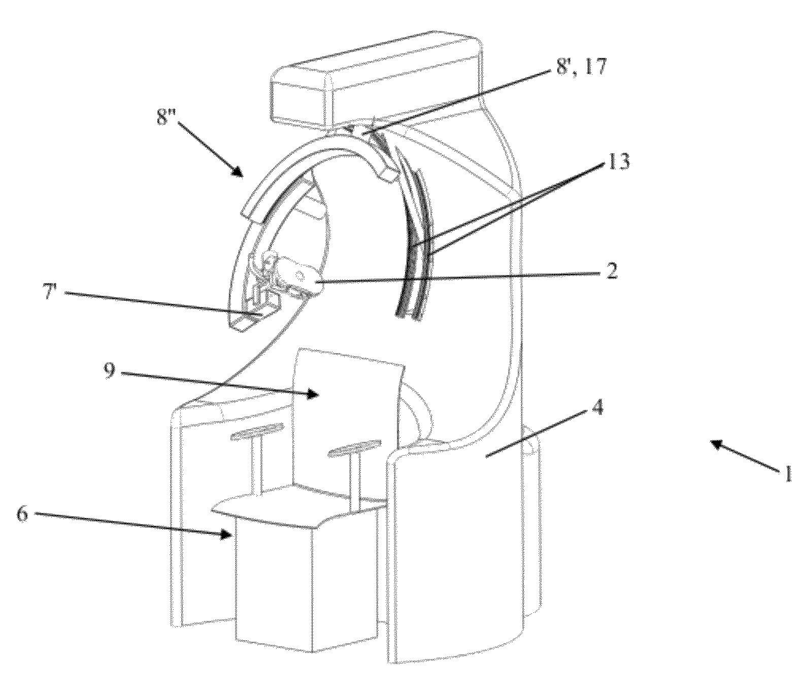
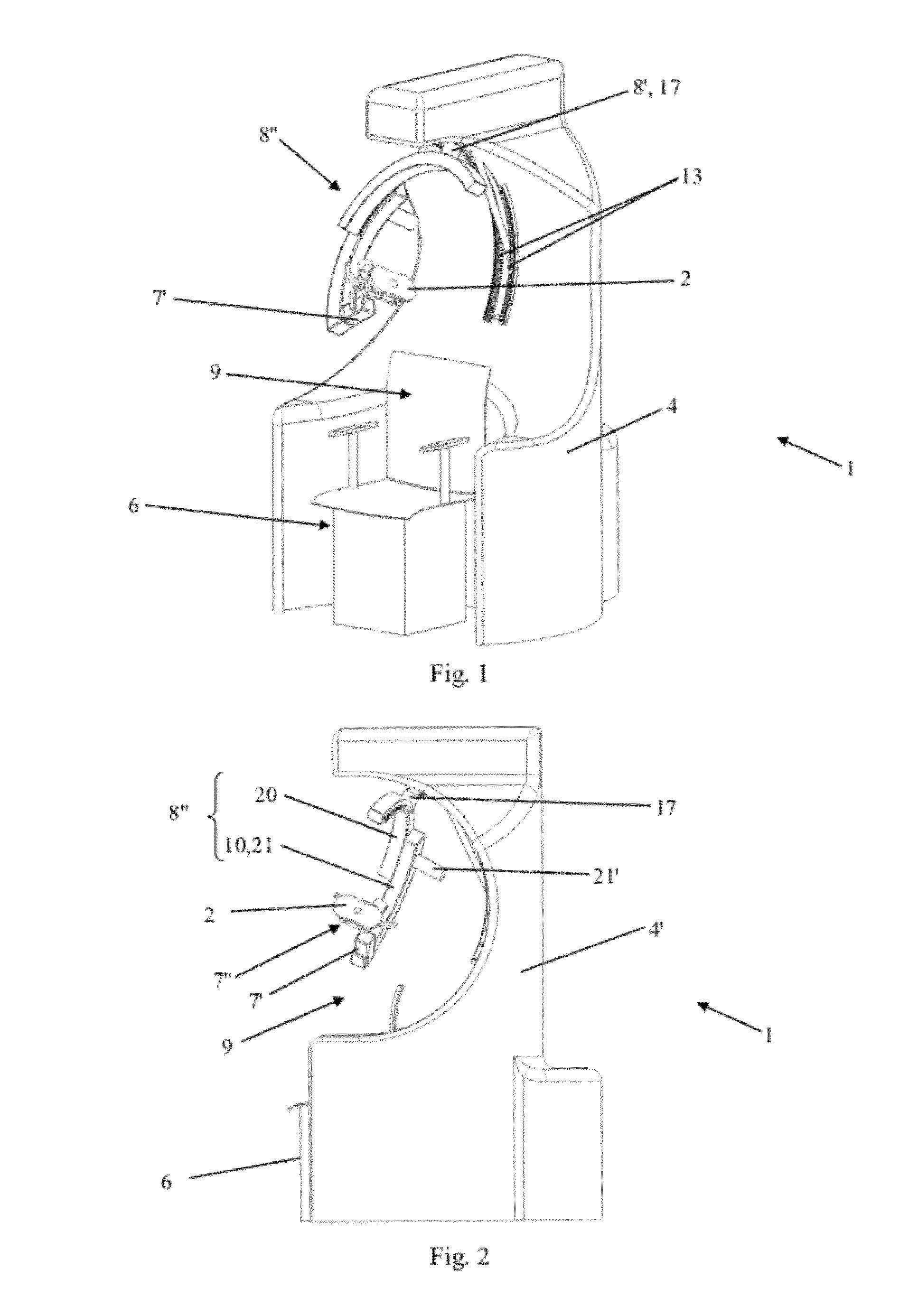
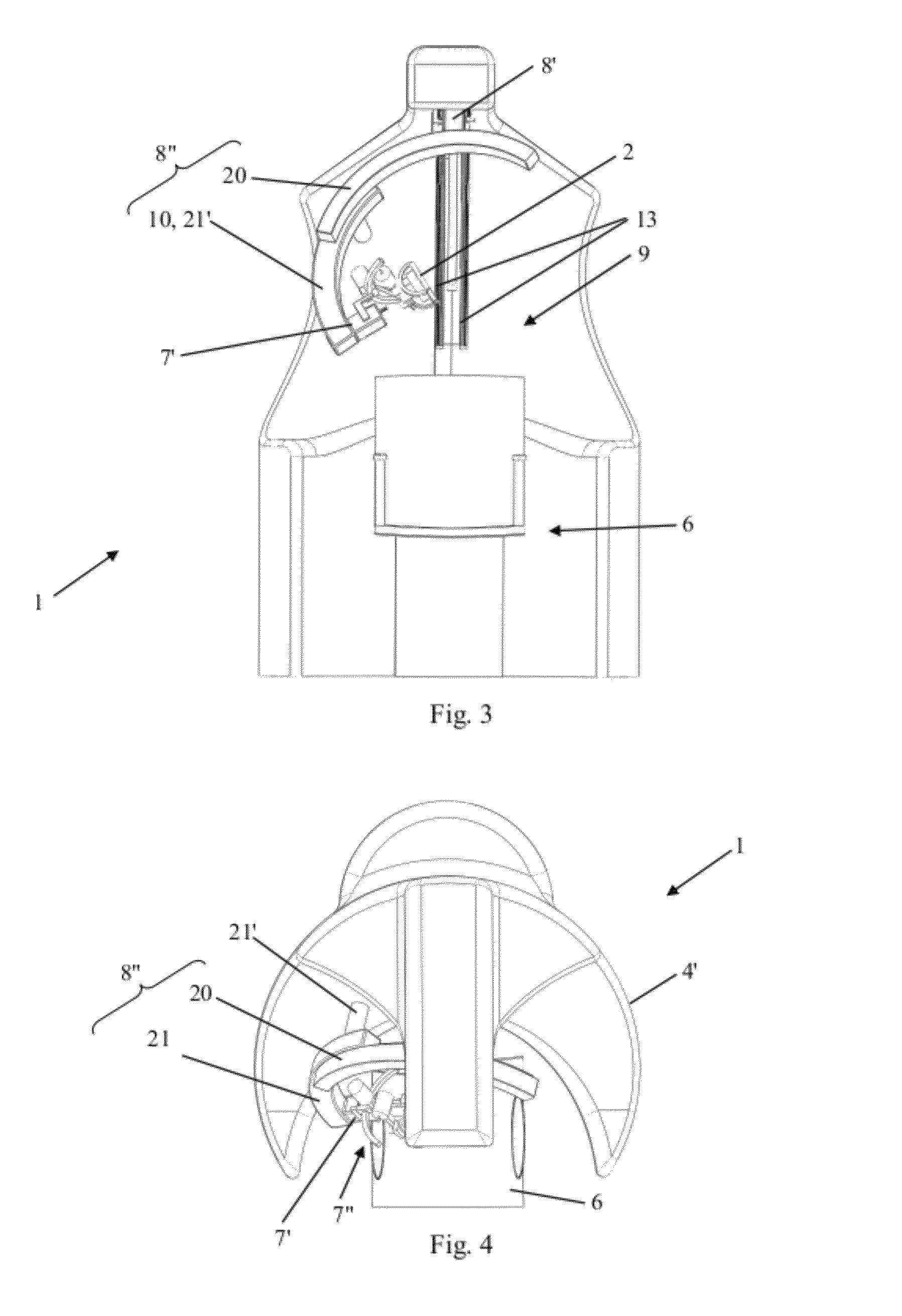
[0047]The latter show a robotized installation 1 for the guided and controlled positioning and movement of a component or instrument 2 for diagnostic or surgical treatment, in particular an imagery probe or a transcranial magnetic stimulation probe or the like, at or around the head 3 of a patient 3′.

[0048]This installation 1 comprises essentially a support structure (frame) 4, covered by a covering and protection casing 4′ and on which are mounted the constituent elements 7 to 31 of a robotic device 5 that forms a serial kinematic chain and that carries the above-mentioned component or instrument 2 at its free and position-controlled end. In addition, an adjustable device 6 for supporting and holding the patient 3′, essentially in the seated position, is part of or is combined with said support structure 4.

[0049]According to the invention, said robotic device 5 consists of at least two 7, 7′, preferably three 7, 7′, 7″, kinematic sub-assemblies that are mutually combined in series,...


PUM


Abstract

Robotized installation for the guided and controlled positioning and movement of a component or an instrument for diagnostic or surgical treatment at or around the head of a patient, whereby the installation includes a robotic device that forms a serial kinematic chain and carries component or instrument at its free and position-controlled end. The robotic device has three kinematic sub-assemblies that are mutually combined in series and include, a first sub-assembly in the form of a rotary-articulation mechanism corresponding to a serial-type, spherical kinematic arrangement with three degrees of freedom, a second sub-assembly in the form of a mechanism with linear translation along an axis, and a third sub-assembly in the form of a second rotary-articulation mechanism, integral with the moving part of the second sub-assembly and also corresponding to a serial-type spherical kinematic arrangement with three degrees of freedom.

Description

BACKGROUND OF THE INVENTION[0001]1. Field of the Invention[0002]This invention relates to the field of robotic installations and devices that have a high precision and a very good safety of use, allowing their implementation in a medical context.[0003]2. Description of the Related Art[0004]This invention more particularly has as its object a robotized installation for the positioning and the movement of a component or instrument, a transcranial magnetic stimulation device that comprises such a robotized installation and a transcranial magnetic stimulation process that implements the above-mentioned device.[0005]In numerous procedures for treating patients or for medical imagery, it is necessary to carry out precise and repeated positionings and movements of components or instruments if necessary over often consistent lengths of time (several tens of minutes).[0006]These experiments are tedious and exhausting for the operator, even when they are assisted mechanically to facilitate th...

Claims


Application Information

Patent Timeline
IPC IPC(8): A61N2/02
CPCA61B6/4441A61B19/2203A61B6/4488A61B19/20A61B6/548A61B2019/2292A61B2019/465A61N2/006A61B2019/2242A61B90/10A61B34/71A61B34/30A61B34/76A61B2090/065
Inventor LEBOSSE, CYRILLERENAUD, PIERREBAYLE, BERNARDDE MATHELIN, MICHELPICCIN, OLIVIERLAROCHE, EDOUARD
Owner CENT NAT DE LA RECHERCHE SCI
Learn More