
Friction lining

a technology of friction lining and lining, which is applied in the direction of friction lining, thin material handling, actuators, etc., can solve the problems of friction lining becoming warped under the action of heat, and achieve the effect of reducing production costs and facilitating production

Inactive Publication Date: 2012-11-06
SCHAEFFLER TECH AG & CO KG
View PDF9 Cites 0 Cited by
  • Summary
  • Abstract
  • Description
  • Claims
  • Application Information

AI Technical Summary

Benefits of technology

[0007]It is therefore an object of the invention to propose a wound friction lining which is easier and less expensive to produce.
[0014]The pressing of the carrier part and the friction part by the hot-pressing process eliminates the need for the complex adhesive bonding of the two parts to one another. It is therefore possible to omit working steps such as adhesive application, adhesive drying and joining of the flashed-off parts, and also to avoid the use of adhesive material. A step equivalent to adhesive bonding during the hot-pressing operation is the polymerization of components of the friction part, for example of the binder, and this leads to a tight bond between the friction part and the carrier part and thus replaces adhesive bonding.
[0017]According to the inventive concept, friction linings produced in this way can be further optimized by adapting the thermal coefficient of the friction part to the expansion of the carrier part. This advantageously takes place in addition to the coordination of the material on the basis of the winding ratio of the blank. It has been found that the coefficient of thermal expansion is influenced by the orientation, predefined by the winding ratio, of the friction lining surface, which is bounded by the radius and the circumference, of the individual strands of the strand material in the radial or circumferential direction. It has also been found that particularly good coordination can be achieved in conjunction with a carrier part of sheet metal when there are winding ratios between 1:2 and 1:6.

Problems solved by technology

Particularly in the case of thin friction linings, the friction lining may become warped under the action of heat.

Method used


Image

  • Friction lining
  • Friction lining

Examples


Embodiment Construction

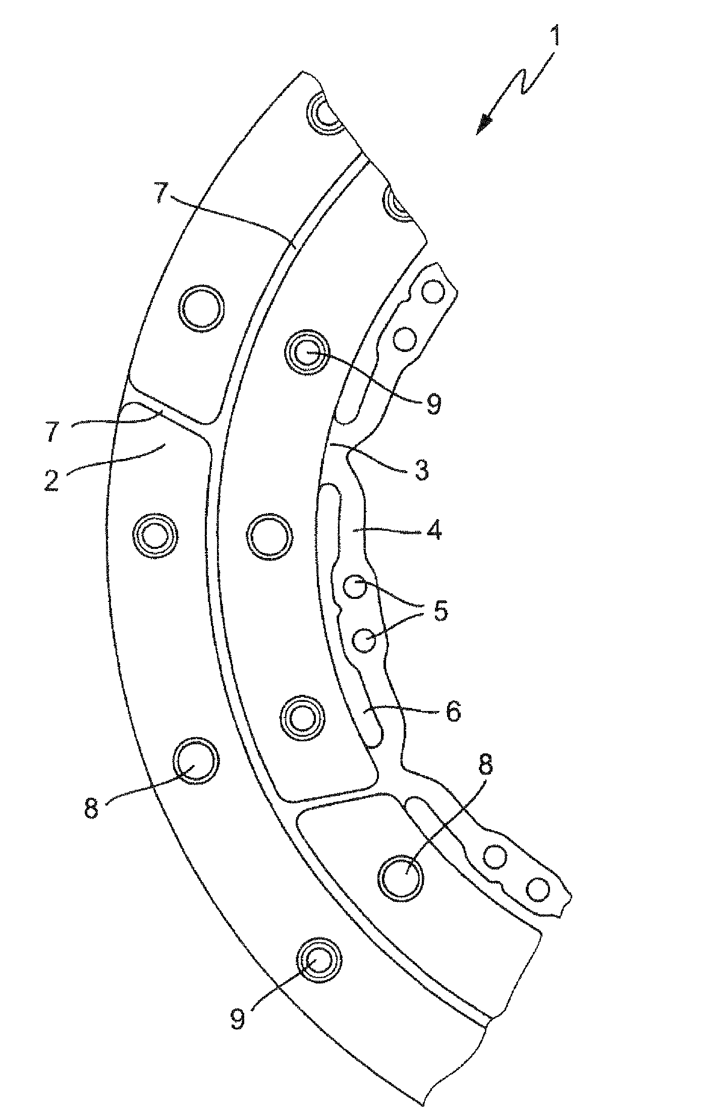
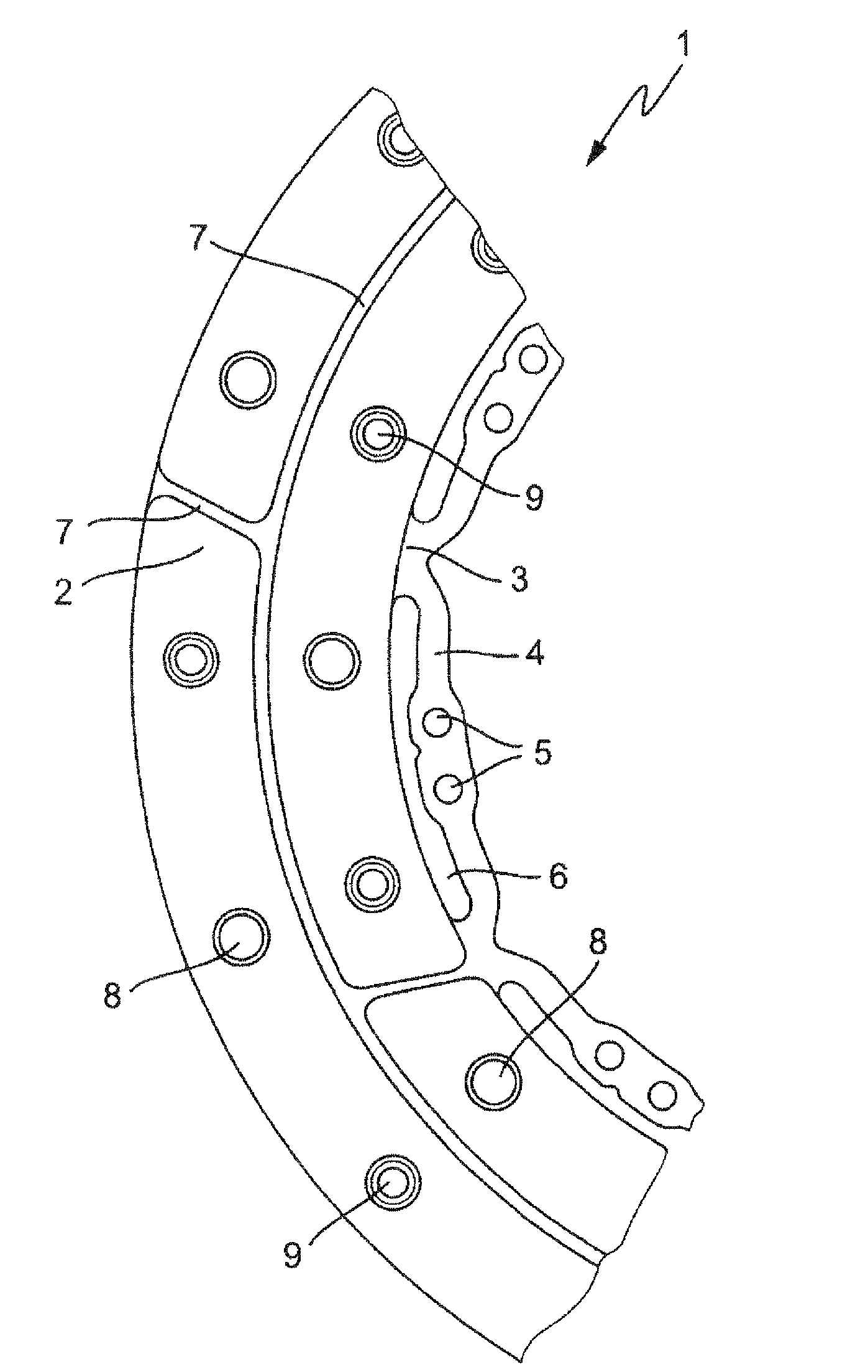
[0021]The invention is explained in more detail on the basis of the single FIGURE. This shows part of a friction lining 1 comprising a friction part 2 and a carrier part 3 of sheet metal as a view onto the friction part 2. The carrier part 3 has the same outside diameter as the friction part 2 and has radially inwardly expanded lugs 4 which are held on the clutch disk by means of openings 5, for example riveted to a flange part of the clutch disk with a further friction lining in a mirror-inverted manner, with lining spring segments placed in between. The cutouts 6 in the carrier part 3, which has preferably been punched, serve to hold the friction linings in an elastic manner on the clutch disk, for example in order to compensate for wobbling vibrations between the drive unit and the transmission input shaft, on which the clutch disk is held.

[0022]The friction part 2 is held on the carrier part 3 by means of a hot-pressing process and is integrally bonded thereto by means of polyme...


PUM

PropertyMeasurementUnit
thermal coefficientaaaaaaaaaa
frictionaaaaaaaaaa
torqueaaaaaaaaaa

Abstract

A friction lining, which has a friction part and a backing part. As a preform, wound from a strand material and treated with a binder, the friction part is subjected to hot pressing. It is suggested that the backing part is subjected to hot pressing together with the preform, so that a bond is created between the friction part and the backing part by the polymerization of the binder.

Description

[0001]This application is a continuation application of PCT / DE2008 / 002145 filed Dec. 22, 2008, which in turn claims the priority DE 10 2008 007 050.5, filed Jan. 31, 2008, the priority of these applications is hereby claimed and these applications are incorporated by reference herein.FIELD OF THE INVENTION[0002]The invention relates to a friction lining and also to a process for producing a friction lining, in particular for clutch disks, comprising a friction part of wound strand material and a carrier part.BACKGROUND OF THE INVENTION[0003]Friction linings of this type are used, in particular, for clutch disks of friction clutches in motor vehicles, a frictional lock between metallic friction surfaces of the friction clutch and the friction linings which, depending on the mode of operation of the friction clutch, can adhere or slip and transmits a corresponding torque from a drive unit to an output.[0004]Owing to the high rotational speeds of the friction clutch, the friction linin...

Claims


Application Information

Patent Timeline
Patent Type & Authority Patents(United States)
IPC IPC(8): F16D69/02
CPCF16D69/0408F16D69/026F16D2069/0483F16D2200/0086Y10T428/213F16D2069/0475
Inventor RUNGE, OLIVERGERBING, TIM-FLORIANWEYEL, THORSTENSPANDERN, CHRISTIAN
Owner SCHAEFFLER TECH AG & CO KG
Learn More