Head-mounted type image display device

a display device and head-mounted technology, applied in closed-circuit television systems, television systems, instruments, etc., can solve the problem of difficult to provide a large diameter of an optical pupil in a transverse direction

Active Publication Date: 2012-11-06
OLYMPUS CORP
View PDF5 Cites 8 Cited by
  • Summary
  • Abstract
  • Description
  • Claims
  • Application Information

AI Technical Summary

Benefits of technology

[0007]Further, as for the optical system that employs a total reflection, an interface with the air should be maintained appropriately on the optical surface. In other words, for the optical surface that performs a total reflection, it is required to prevent water droplets and dust from entering into the air-spacing (what is called an air gap). In particular, it is important for the optical system for a head-mounted type image display device to provide an air gap that can withstand the external environment such as rain and wind while satisfying the requirements such as compact and lightweight.
[0008]Consequently, in the present invention, a head-mounted type image display device whose width of an optical pupil is large in the direction of interpupillary distance is provided. Further, the head-mounted type image display device is compact, lightweight and can withstand the external environment.
[0018]According to the present invention, a head-mounted type image display device having a large width of the optical pupil in the direction of interpupillary distance can be provided. Further, the head-mounted type image display device is compact, lightweight and can withstand the external environment.

Problems solved by technology

However, for the conventional optical system described in the above-mentioned related art, it is difficult to provide a large diameter of an optical pupil in a transverse direction.

Method used


Image

  • Head-mounted type image display device
  • Head-mounted type image display device
  • Head-mounted type image display device

Examples


first embodiment

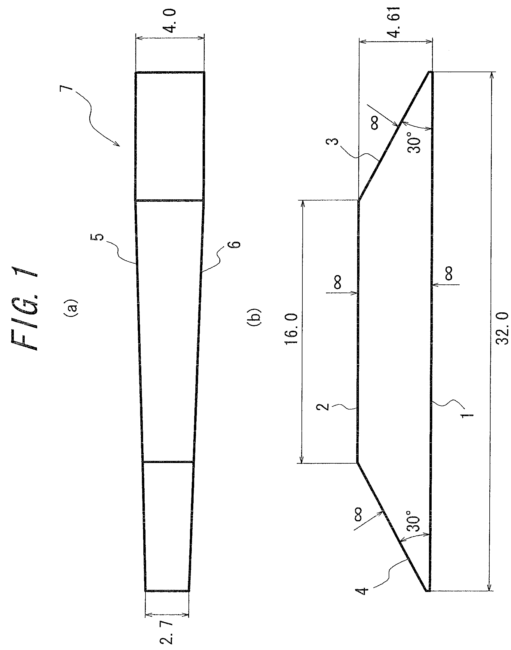
[0031]FIG. 1 is a diagram illustrating a hexahedron prism 7 used to the embodiment of the present invention. FIG. 1(a) is an elevation view and FIG. 1(b) is a plan view. The hexahedron prism 7 shown in FIG. 1 includes a first optical surface 1, a second optical surface 2, a third optical surface 3, a fourth optical surface 4, a fifth optical surface 5 and a sixth optical surface 6.

[0032]The first optical surface 1 and the second optical surface 2 are opposed to each other in the hexahedron and are approximately parallel to each other. The third optical surface 3 and the fourth optical surface 4 are opposed to each other in the hexahedron and are inclined to face each other with respect to the first optical surface 1. In other words, the third optical surface 3 and the fourth optical surface 4 constitute what is called an inversed V shape separated at the top. Further, the inner angle θ between the first optical surface 1 and the third optical surface 3 is approximately equal to the ...

second embodiment

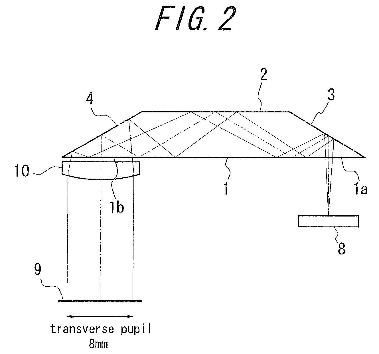
[0046]Next, another embodiment of the light guiding optical system in accordance with the present invention is illustrated with reference to FIG. 4.

[0047]The light guiding optical system shown in FIG. 4 is constituted by the hexahedron prism 7 and an integrally molded optical member 11, and outputs the image light from the image display element 8 to the eye pupil 9 of the user.

[0048]The hexahedron prism 7 shown in FIG. 4 can be the same hexahedron prism 7 illustrated in the first embodiment. In other words, the hexahedron prism 7 shown in FIG. 4 includes the first optical surface 1, the second optical surface 2, the third optical surface 3, the fourth optical surface 4, the fifth optical surface 5 and the sixth optical surface 6. The first optical surface 1 and the second optical surface 2 are opposed to each other in the hexahedron and are approximately parallel to each other. The third optical surface 3 and the fourth optical surface 4 are opposed to each other in the hexahedron a...

third embodiment

[0053]Next, still another embodiment of the light guiding optical system according to the present invention is illustrated with reference to FIG. 6.

[0054]The light guiding optical system shown in FIG. 6 is constituted by the hexahedron prism 7 and the integrally molded optical member 11 and outputs the image light from the image display element 8 to the eye pupil 9 of the user.

[0055]The hexahedron prism 7 shown in FIG. 6 can be the same hexahedron prism 7 described in the first embodiment. In other words, the hexahedron prism 7 shown in FIG. 6 includes the first optical surface 1, the second optical surface 2, the third optical surface 3, the fourth optical surface 4, the fifth optical surface 5 and the sixth optical surface 6. The first optical surface 1 and the second optical surface 2 are opposed to each other in the hexahedron and are approximately parallel to each other. The third optical surface 3 and the fourth optical surface 4 are opposed to each other in the hexahedron and...


PUM


Abstract

A hexahedron prism in which a first optical surface and a second optical surface opposed to each other are approximately parallel, the inner angles θ between the first optical surface and each of a third optical surface and a fourth optical surface opposed to each other are equal, a fifth optical surface and a sixth optical surface opposed to each other are configured inclining toward each other and the distance therebetween becomes narrow from the third optical surface to the fourth optical surface, and further, a light beam from a image display element enters through a first partial optical surface into the hexahedron prism, reflects inside the prism and is emitted through a second partial optical surface to an eye pupil of a user.

Description

CROSS-REFERENCE TO RELATED APPLICATION[0001]The present application claims priority from Japanese Application No. 2009-074420, filed on Mar. 25, 2009, the content of which is incorporated herein by reference.FIELD OF THE INVENTION[0002]The present invention relates to a head-mounted type image display device.BACKGROUND OF THE INVENTION[0003]In recent years, what is called a head-mounted type image display device (or a head-mount display) has attracted attention. As for such a head-mounted type image display device, the video image light or the still image light emitted from a compact image display element (e.g. a liquid crystal display panel and an organic electroluminescence) is guided to a user's eye pupil by an optical technique such as a mirror or a prism.[0004]In this case, methods for superimposing the external light and the image light include methods that use an optical element (what is called a combiner) such as a half mirror and a pupil division method. The pupil division ...

Claims


Application Information

Patent Timeline
Patent Type & Authority Patents(United States)
IPC IPC(8): G09G5/00
CPCG02B17/006G02B17/0856G02B27/0172G02B17/086G02B2027/0178G02B2027/0123
Inventor IBA, YOICHISUGIHARA, RYOHEITATSUTA, SEIJI
Owner OLYMPUS CORP
Why Eureka
Try Eureka