Control device for legged mobile robot

a mobile robot and control device technology, applied in the direction of electric programme control, program control, instruments, etc., can solve the problems of difficult to achieve still faster motion of the robot, difficult to ensure high responsiveness in adjusting the desired motion, and inability to generate desired motion by analytical arithmetic processing, etc., to achieve high dynamic accuracy, high responsiveness, and high reliability

Active Publication Date: 2012-11-06
HONDA MOTOR CO LTD
View PDF14 Cites 44 Cited by
  • Summary
  • Abstract
  • Description
  • Claims
  • Application Information

AI Technical Summary

Benefits of technology

[0030]In this case, the first model external force manipulated variable to be input to the first motion determining unit has the low frequency component of the model basic manipulated variable as the major component thereof. This makes it possible to sequentially determine the instantaneous value of the first motion such that the posture state amount error exhibiting a relatively slow change is properly brought close to zero even if the execution cycle of the processing by the first motion determining unit is a relatively long cycle.
[0073]As a result, the time series of the instantaneous value of a desired motion that permits continuous stable motions of the robot can be properly determined.

Problems solved by technology

Frequently, such a desired motion cannot be generated by analytical arithmetic processing.
However, if the cycle of the processing for calculating a desired motion has to be set to rather long time, as described above, then it is difficult to ensure high responsiveness in adjusting the desired motion when the actual posture of the robot deviates from a desired posture.
This in turn inconveniently makes it difficult to achieve still faster motions of the robot.

Method used


Image

  • Control device for legged mobile robot
  • Control device for legged mobile robot
  • Control device for legged mobile robot

Examples


second embodiment

[Second Embodiment]

[0573]Referring now to FIG. 25, a second embodiment of the present invention will be described. The present embodiment differs from the first embodiment only partially in the processing carried out by a control unit 26. Hence, in the description of the present embodiment, for the constituent units or functional units that are equivalent to those in the first embodiment, the same reference numerals as those used in the first embodiment will be used, and detailed explanation thereof will be omitted.

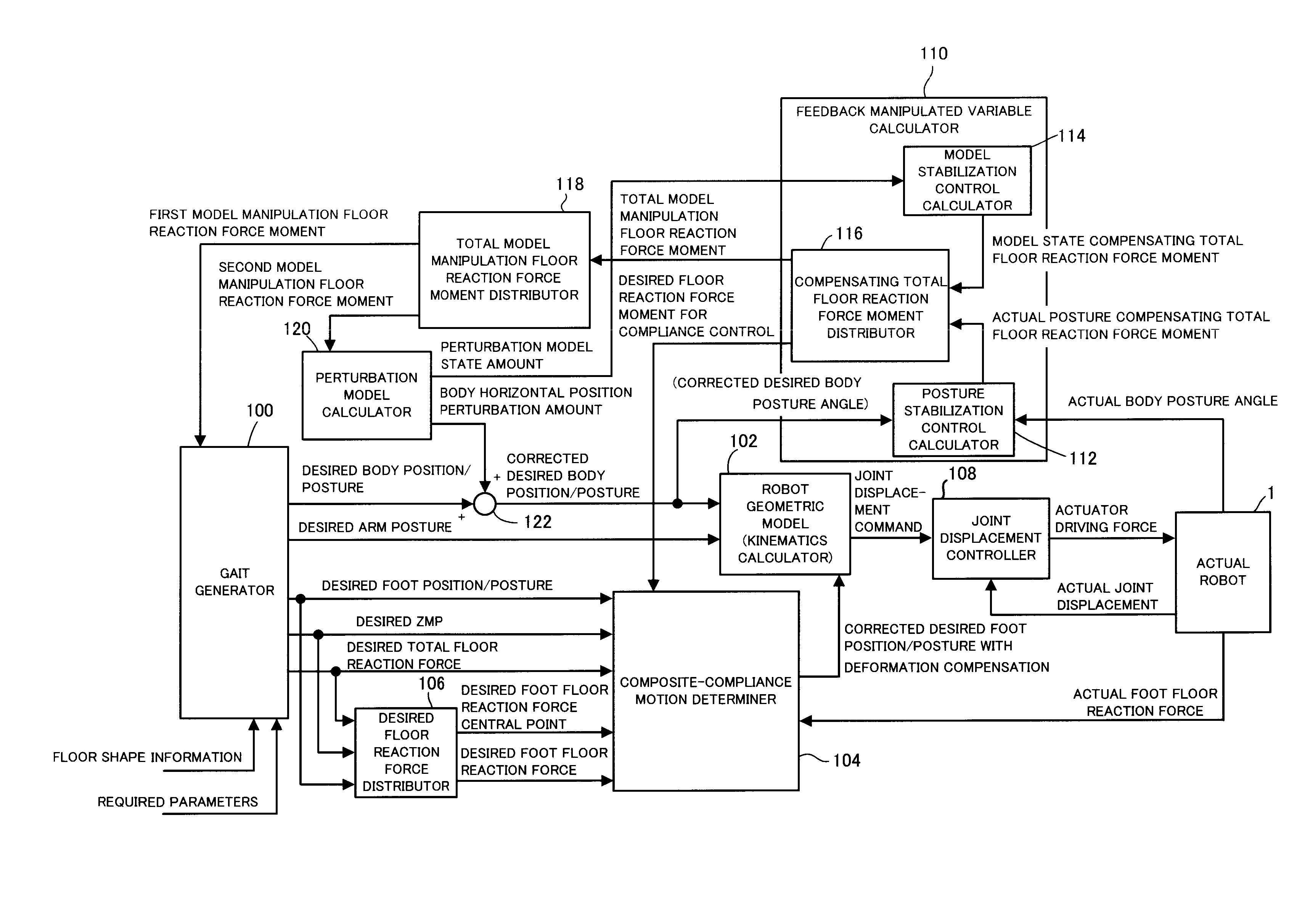
[0574]The gait generator 100 described in the first embodiment uses an instantaneous value sampled at the control cycle (arithmetic processing cycle) Δt of the gait generator 100 out of the time series of the first model manipulation floor reaction force moment output from the total model manipulation floor reaction force moment distributor 118, and carries out the processing for determining the instantaneous value of a current time's gait (the processing in S032 of FIG. ...

third embodiment

[Third Embodiment]

[0589]Referring now to FIG. 26 to FIG. 28, a third embodiment of the present invention will be described. The present embodiment differs from the first embodiment only partially in the processing carried out by a control unit 26. Hence, in the description of the present embodiment, for the constituent units or functional units that are equivalent to those in the first embodiment, the same reference numerals as those used in the first embodiment will be used, and detailed explanation thereof will be omitted.

[0590]In the first embodiment, the second model manipulation floor reaction force moment as the high frequency component of the total model manipulation floor reaction force moment has been fed back to the inverted-pendulum type perturbation dynamic model (the dynamic model in FIG. 22), and the body horizontal position perturbation amount indicative of the correction amount of a desired body position / posture has been calculated by the perturbation model calculato...

fourth embodiment

[Fourth Embodiment]

[0646]Referring now to FIG. 29 and FIG. 30, a fourth embodiment of the present invention will be described. The present embodiment differs from the aforesaid third embodiment only in the processing carried out by the total model manipulation floor reaction force moment distributor. Hence, the constituent units or functional units except for the total model manipulation floor reaction force moment distributor will be assigned the like reference numerals as those used in the third embodiment, and detailed explanation thereof will be omitted.

[0647]Referring to FIG. 29, a total model manipulation floor reaction force moment distributor 131 in the present embodiment determines a first model manipulation floor reaction force moment, a first “a” model manipulation floor reaction force moment, and a first “b” model manipulation floor reaction force moment from a total model manipulation floor reaction force moment and outputs the determined moments, and outputs the determ...


PUM


Abstract

A control device for a legged mobile robot has a first motion determiner which sequentially determines the instantaneous value of a first motion of a robot by using a first dynamic model and a second motion determiner which sequentially determines the instantaneous value of a second motion of the robot by using a second dynamic model, and sequentially determines a desired motion of the robot by combining the first motion and the second motion. A low frequency component and a high frequency component of a feedback manipulated variable having a function for bringing a posture state amount error, which indicates the degree of the deviation of an actual posture of the robot from a desired posture, close to zero are fed back to the first motion determiner and the second motion determiner, respectively.

Description

BACKGROUND OF THE INVENTION[0001]1. Field of the Invention[0002]The present invention relates to a control device for a legged mobile robot, such as a bipedal walking robot.[0003]2. Description of the Related Art[0004]As a technique for enhancing the stability of the posture of a legged mobile robot, which travels by moving a plurality of legs extended from a base body, the technique disclosed in, for example, Japanese Patent No. 3269852, has been proposed by the applicant of the present application.[0005]According to the technique, a state amount deviation of an actual posture of the body of a robot from a desired posture is observed, and an operational moment (an operational moment about a desired ZMP) to be additionally applied to the robot is calculated according to a PD law (proportional-differential law) from the observed value of the state amount deviation as the feedback manipulated variable (control input) required to converge the state amount deviation to zero.[0006]Furthe...

Claims


Application Information

Patent Timeline
Patent Type & Authority Patents(United States)
IPC IPC(8): G05B19/04
CPCB62D57/032G06N3/008
Inventor YOSHIIKE, TAKAHIDEKANEKO, HIROYUKIORITA, ATSUO
Owner HONDA MOTOR CO LTD
Why Eureka
Try Eureka