Method and system for calculating misalignment of rotational body

a technology of rotational body and misalignment, which is applied in the direction of mechanical measuring arrangements, electrical/magnetic diameter measurements, instruments, etc., can solve the problems of difficult elimination of abnormal values and expected accuracy, and achieves easy determination, increased reliability of measurement work, and convenient maintenance work

Active Publication Date: 2012-11-06
MITSUBISHI POWER LTD
View PDF23 Cites 33 Cited by
  • Summary
  • Abstract
  • Description
  • Claims
  • Application Information

AI Technical Summary

Benefits of technology

[0029]With the configuration in the first solution, the misalignment data of the most probable circle can be calculated by a simple method, thereby facilitating maintenance work such as disassembly and assembly of the rotational body.
[0036]With the configuration in the eighth solution, the abnormal value of the measured value can be immediately eliminated, thereby achieving a system with quick, reliable maintenance.

Problems solved by technology

However, the methods disclosed in Patent Citations 1 and 2 require an enormous amount of calculation; therefore, a simpler method is desired.
Thus, the influence of the abnormal value prevents expected accuracy from being obtained, and eliminating the abnormal value is difficult.

Method used


Image

  • Method and system for calculating misalignment of rotational body
  • Method and system for calculating misalignment of rotational body
  • Method and system for calculating misalignment of rotational body

Examples


example 1

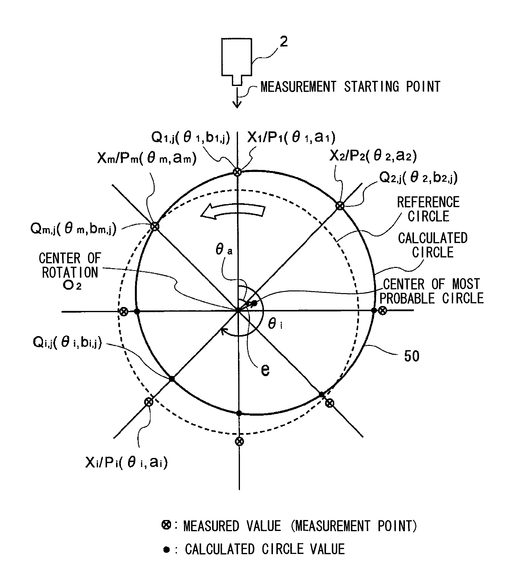
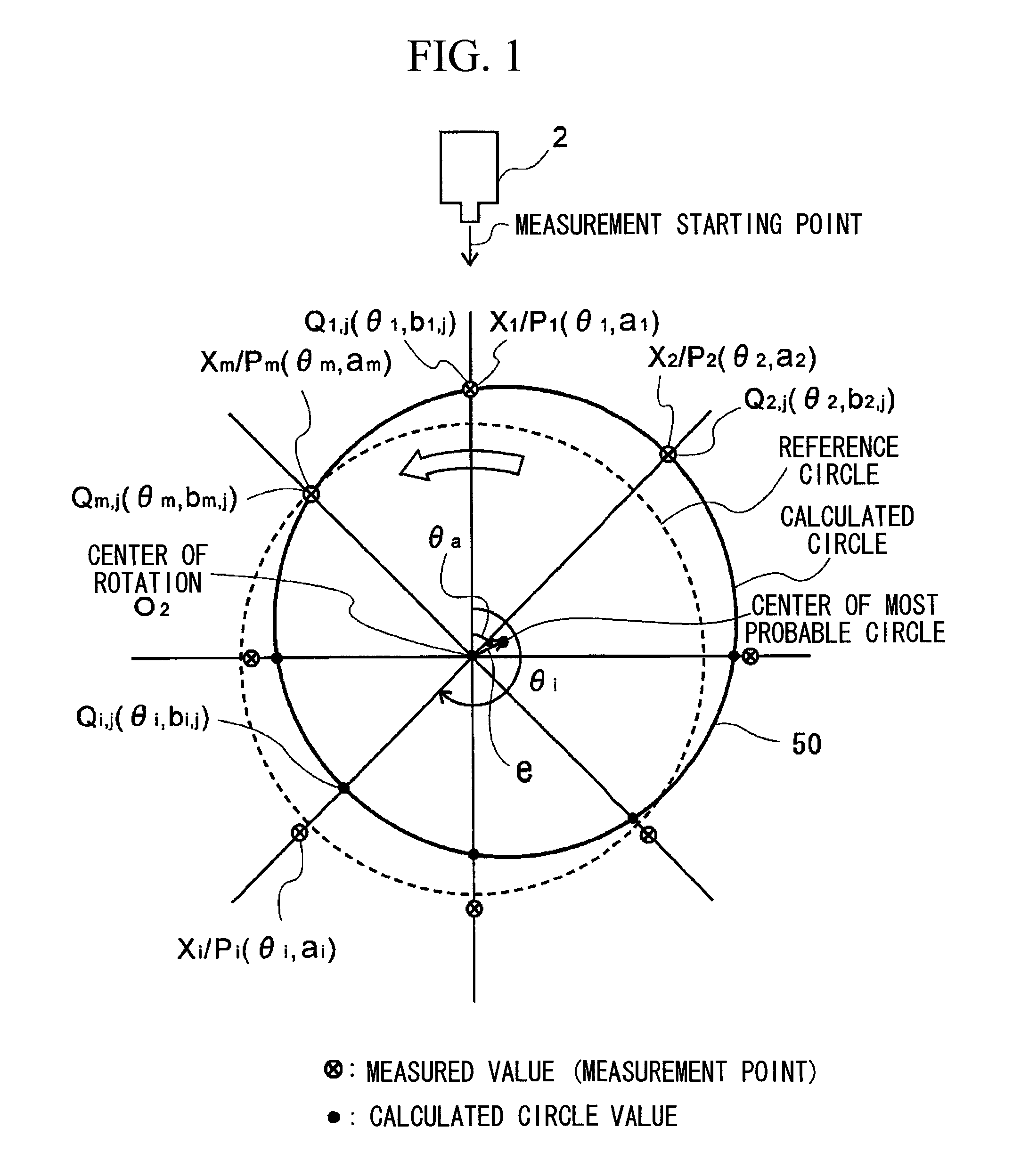
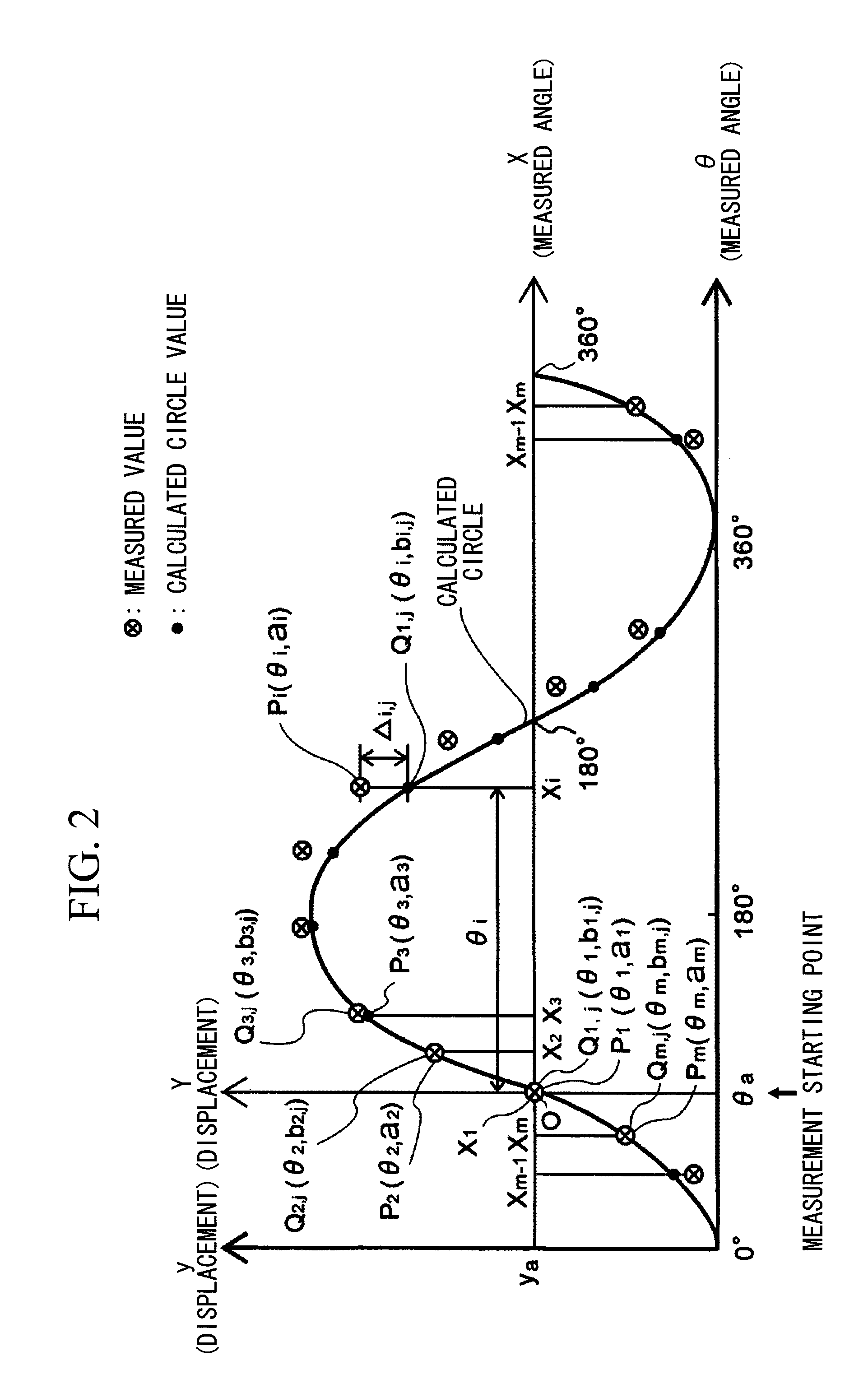
[0123]A specific example of the method for calculating misalignment at the time of normal measurement will be described taking the rotor disk that constitutes the gas turbine rotor 1 as an example. In this example, the rotor disk is circumferentially divided into eight sections, and a deflection amount at each measurement point is measured to calculate misalignment data.

[0124]FIG. 7 shows measured values and most probable circle calculated circle values for measured angles at eight measurement points as Example 1, and shows a misalignment amount and a misalignment angle included in misalignment data of the most probable circle. In this example, three points X1, X4 and X5 are used as measurement points for calculating a calculated circle. The most probable circle calculated circle value refers to a calculated circle value at each measurement point for a most probable circle in this example. FIG. 8 schematically shows the relationship as a relationship among the reference circle, the ...

example 2

[0125]An example of a case where an abnormal value appears in the measured value at the time of measurement of the rotor disk of the gas turbine rotor 1 will be described below. This example shows a case where an abnormal value appears at one measurement point (measurement point X5) among the eight measurement points.

[0126]Example 2 in FIG. 7 shows measured values and most probable circle calculated circle values at the measurement points, and shows a misalignment amount and a misalignment angle. In this example, three points X1, X2 and X8 are used as measurement points for calculating a calculated circle. FIG. 9 shows most probable circle error amounts for measured values and most probable circle calculated circle values in this example. In FIG. 7, according to the present invention, even if the abnormal value in Example 2 appears, a final misalignment amount and misalignment angle are substantially the same as in Example 1 at the time of normal measurement, and there is little inf...


PUM


Abstract

In a method of calculating misalignment of a rotational body, radial displacement values are measured using a displacement gauge. A calculation part performs the steps of deriving radial displacement amounts of the rotational body for at least four or more measurement points along an outer surface while rotating the rotational body, selecting three arbitrary points to calculate a circle, calculating circle values for all the measurement points, calculating differences between the calculated circle values and the radial displacement amounts as error amounts, summing the error amounts to derive a total error amount, repeating circle calculation for different combinations and calculating a total error amount for each calculated circle, selecting a circle with a minimum total error amount as a most probable circle, and calculating deviation between the center of the most probable circle and the center of rotation of the rotational body.

Description

RELATED APPLICATIONS[0001]The present application is the US national phase of, and claims priority from, International Application Number PCT / JP2008 / 061864, filed Jun. 30, 2008, the disclosure of which is hereby incorporated by reference herein in its entirety.TECHNICAL FIELD[0002]The present invention relates to a method and a system for calculating misalignment of a rotational body.BACKGROUND ART[0003]Generally, axial deformation or misalignment that occurs in a rotational body causes imbalance of the rotational body, which may cause shaft vibration during operation. Excessive shaft vibration causes an abnormality in a bearing part and prevents normal operation. A further progress of the excessive vibration may lead to a break of the shaft. Thus, to prevent such a break, it is important to keep axial deformation or misalignment of the rotational body within an acceptable value.[0004]Rotational bodies covered by the present invention include a gas turbine rotor, and also rotors for...

Claims


Application Information

Patent Timeline
Patent Type & Authority Patents(United States)
IPC IPC(8): G01C9/00
CPCG01B21/24
Inventor IHARA, KEISUKESAKAE, TOSHIYUKI
Owner MITSUBISHI POWER LTD
Why Eureka
Try Eureka