Electric power steering assembly
a technology of electric power steering and assembly, which is applied in the direction of vehicle sub-unit features, vehicle design optimization, etc., can solve the problem of unsatisfactory noise produced by one or more of the associated components of the rack drive assembly
- Summary
- Abstract
- Description
- Claims
- Application Information
AI Technical Summary
Benefits of technology
Problems solved by technology
Method used
Image
Examples
first embodiment
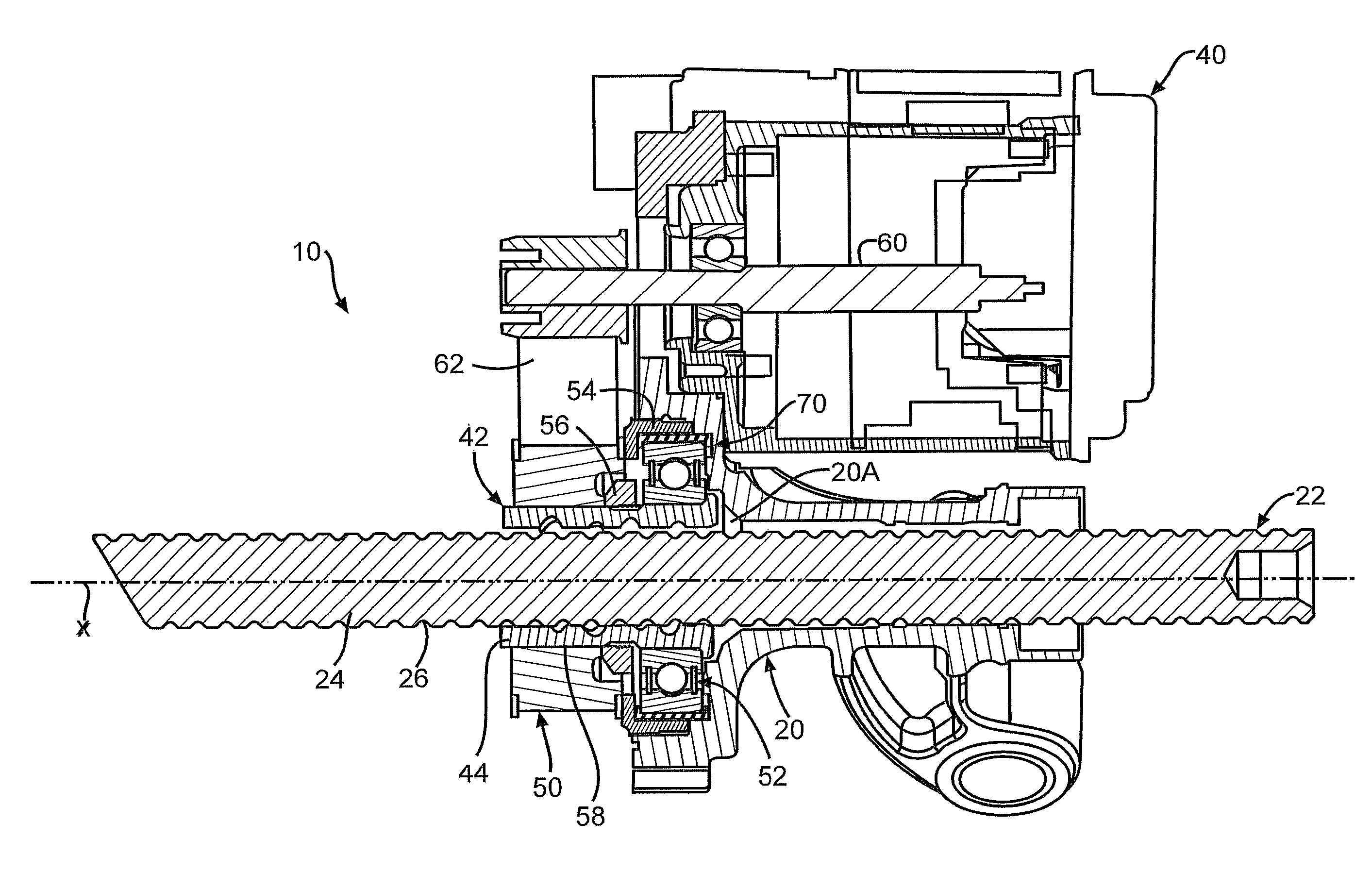
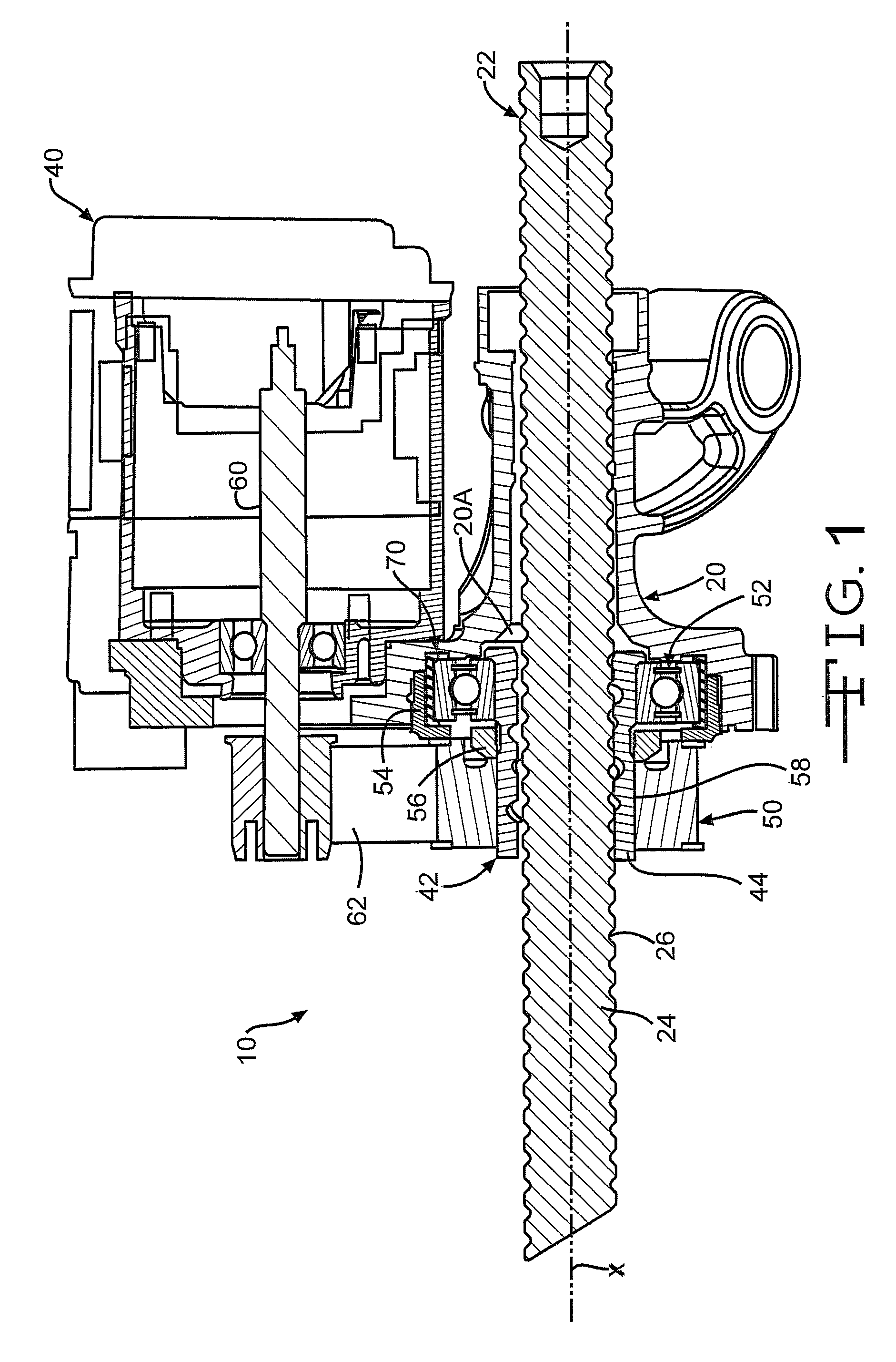
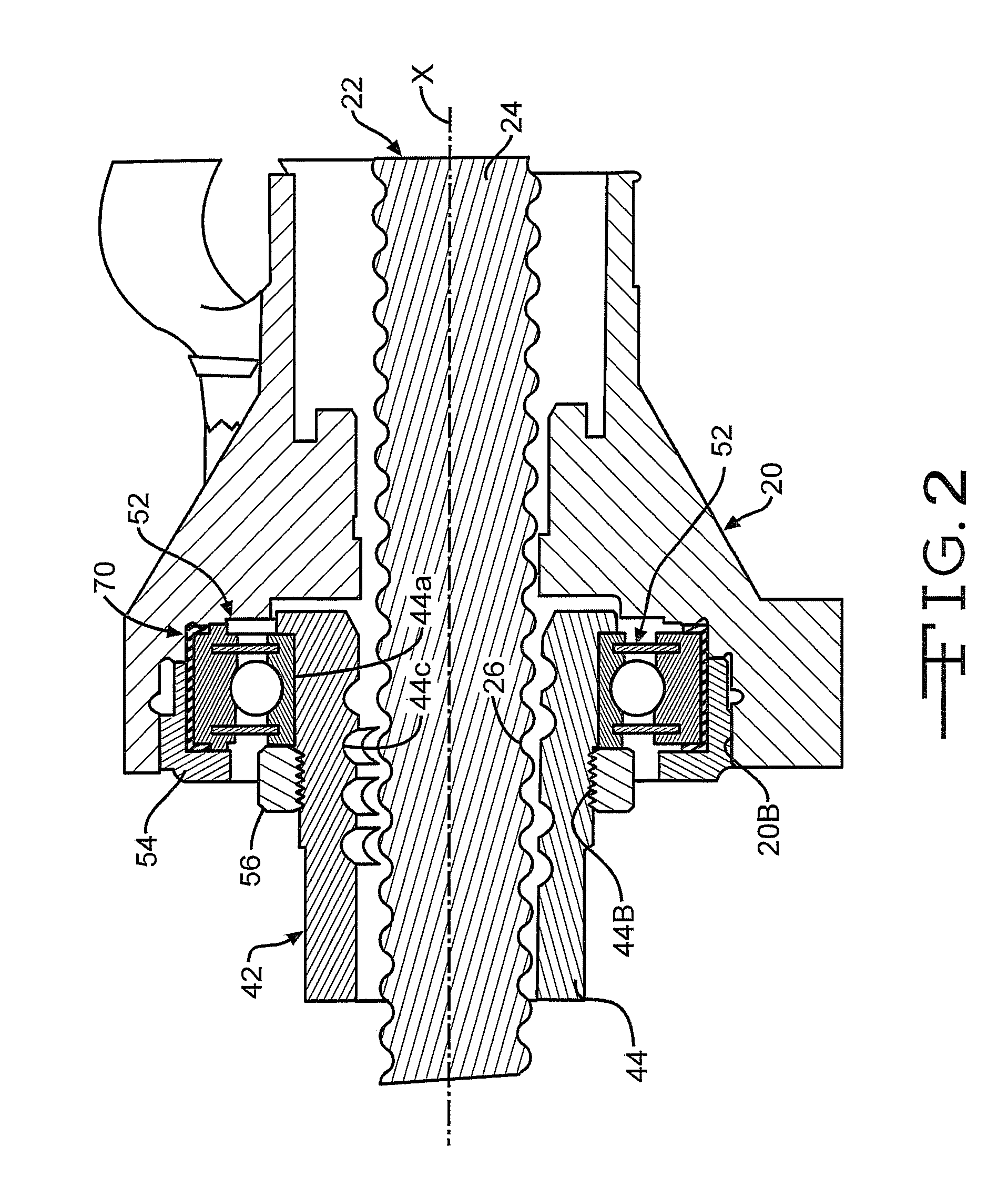
[0016]Referring now to FIGS. 1-3, there is illustrated a vehicle electric power steering assembly, indicated generally at 10, constructed in accordance with the present invention. The illustrated vehicle electric power steering assembly 10 is a vehicle electric belt driven rack drive steering assembly and is associated with the front driven wheels (not shown) of the vehicle. The general structure and operation of the electric power steering assembly 10 is conventional in the art. Thus, only those portions of the electric power steering assembly 10 which are necessary for a full understanding of this invention will be explained and illustrated in detail. Also, although this invention will be described and illustrated in connection with the particular electric power steering assembly 10 disclosed herein, it will be appreciated that this invention may be used in connection with other electric power steering assemblies. For example, the invention may be used in connection with other ele...
second embodiment
[0029]Turning now to FIG. 4 and using like reference numbers to indicate corresponding parts, there is illustrated a portion of a vehicle electric power steering assembly, indicated generally at 80, constructed in accordance with the present invention. In this embodiment, a damper 82 is provided having one or more metal plates or otherwise rigid members disposed therein, preferably disposed therein by integrally molding the plates or members therein.
[0030]In the illustrated embodiment, the damper 82 is preferably provided with at least integrally molded metal plates 84A and 86A disposed at least within a portion of one or both of a pair of sides or legs 84 and 86, respectively, thereof. Preferably, this embodiment of the damper 82 would not be molded onto the associated bearing assembly 52 but would be preferably fitted or stretched thereon prior to assembly. However, if so desired, the damper 82 may be molded onto the bearing assembly 52. Alternatively, the shape, construction and / ...
third embodiment
[0031]Turning now to FIG. 5 and using like reference numbers to indicate corresponding parts, there is illustrated a portion of a vehicle electric power steering assembly, indicated generally at 100, constructed in accordance with the present invention. In this embodiment, the vehicle electric power steering assembly 100 includes a damper or insulator, indicated generally at 101, which is operatively disposed between selected adjacent surfaces of the bearing assembly 52, the spanner nut 54 and the housing 20.
[0032]In this embodiment, the damper 101 is comprised of a pair of dampers 102 and 102′. In the illustrated embodiment, each of the pair of dampers 102 and 102′ are shown as being identical to each other; however, the construction of the pair of dampers 102 and 102′ can be different from each other if so desired. For discussion purposes, since the dampers 102 and 102′ are illustrated as being identical, only the construction of the damper 102 will be discussed below in detail. H...
PUM
 Abstract
Description
Claims
Application Information
 - R&D
- Intellectual Property
- Life Sciences
- Materials
- Tech Scout
- Unparalleled Data Quality
- Higher Quality Content
- 60% Fewer Hallucinations
Browse by: Latest US Patents, China's latest patents, Technical Efficacy Thesaurus, Application Domain, Technology Topic, Popular Technical Reports.
© 2025 PatSnap. All rights reserved.Legal|Privacy policy|Modern Slavery Act Transparency Statement|Sitemap|About US| Contact US: help@patsnap.com


