Speed change transmission system
a transmission system and transmission shaft technology, applied in fluid gearings, transmission casings, transportation and packaging, etc., can solve the problems of small size in the fore and aft direction of the transmission case, compact size, etc., to achieve effective absorption of torque variations in the double transmission state, high transmission efficiency of the clutches, and effective absorption of torque variations
- Summary
- Abstract
- Description
- Claims
- Application Information
AI Technical Summary
Benefits of technology
Problems solved by technology
Method used
Image
Examples
first embodiment
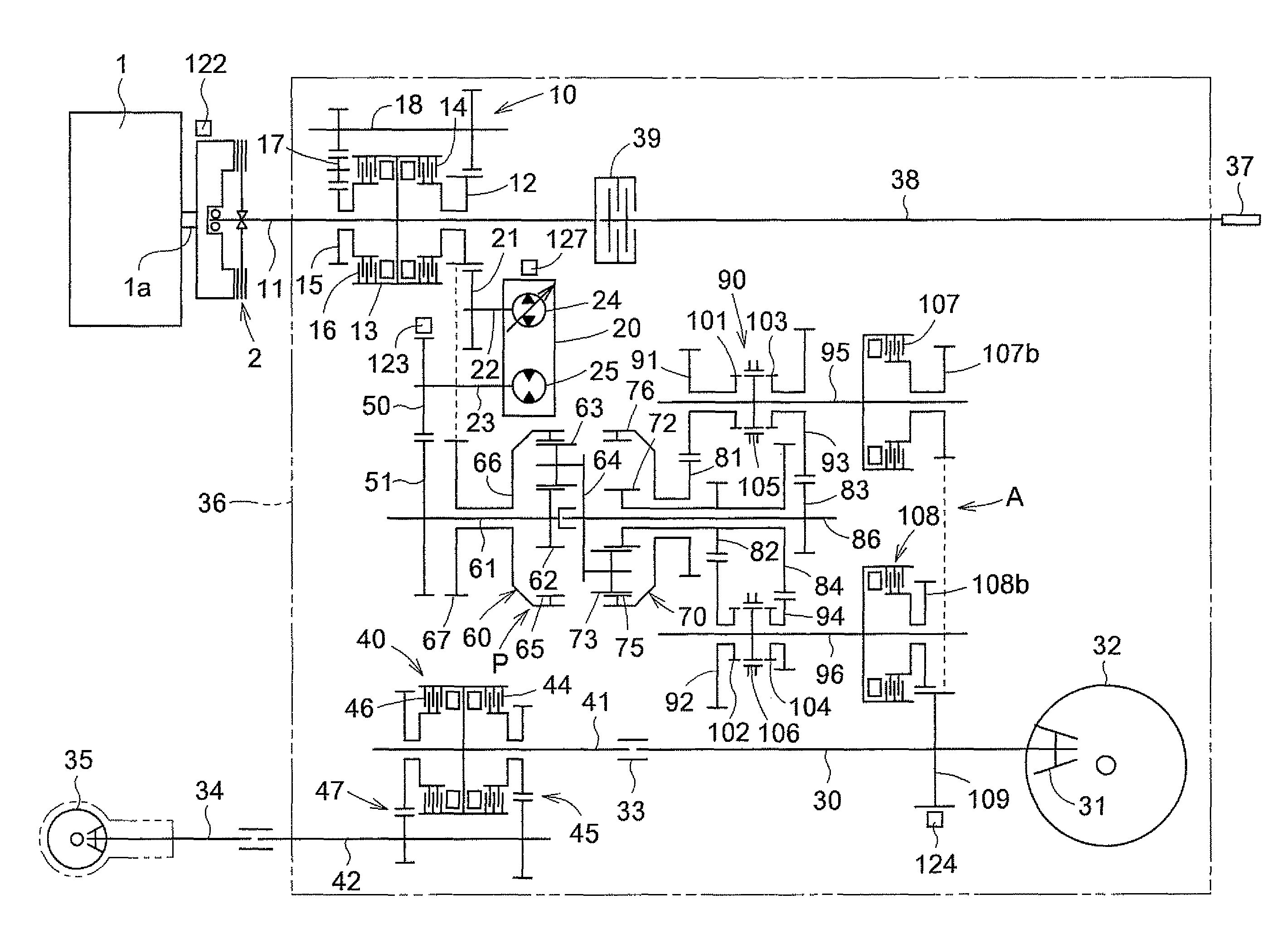
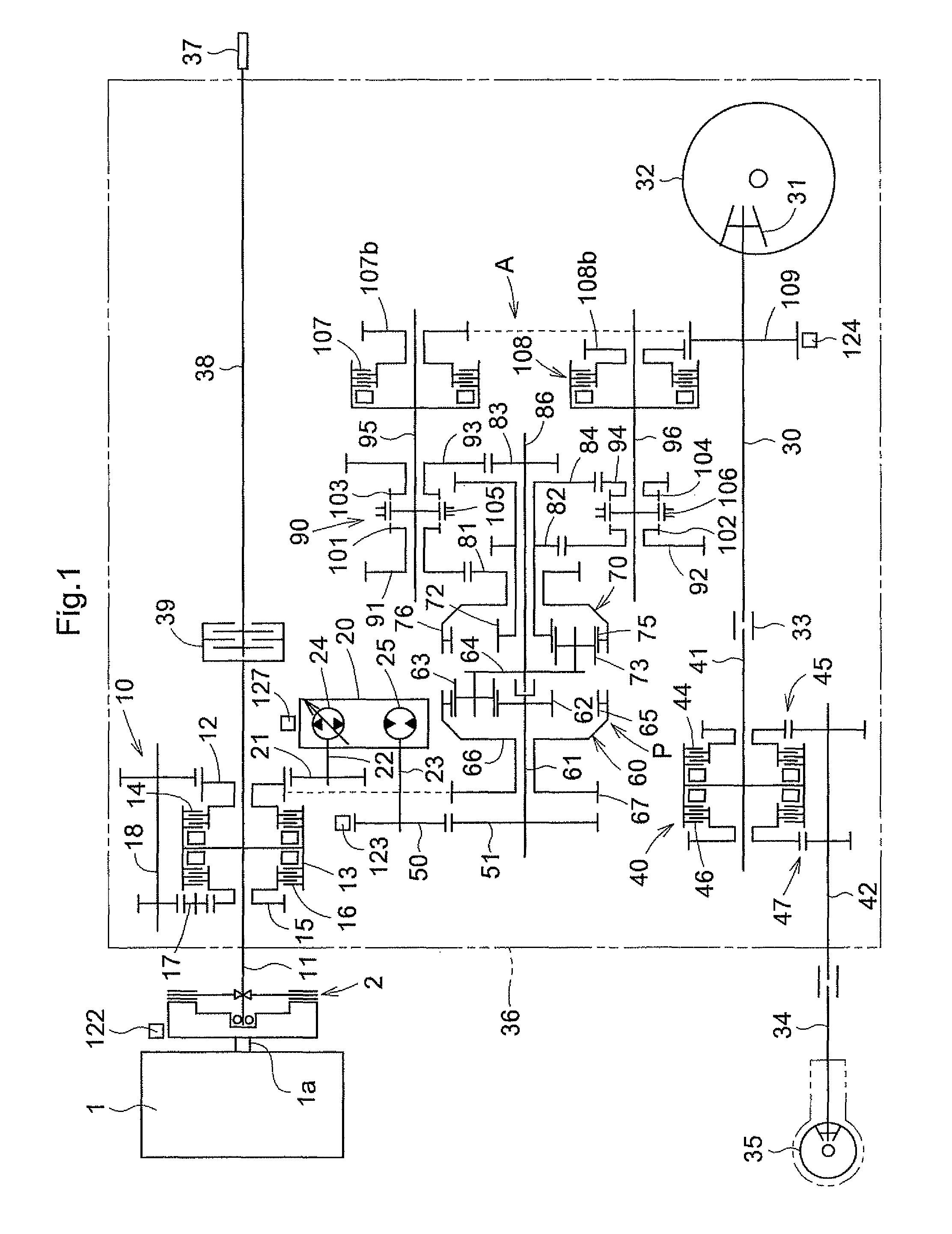
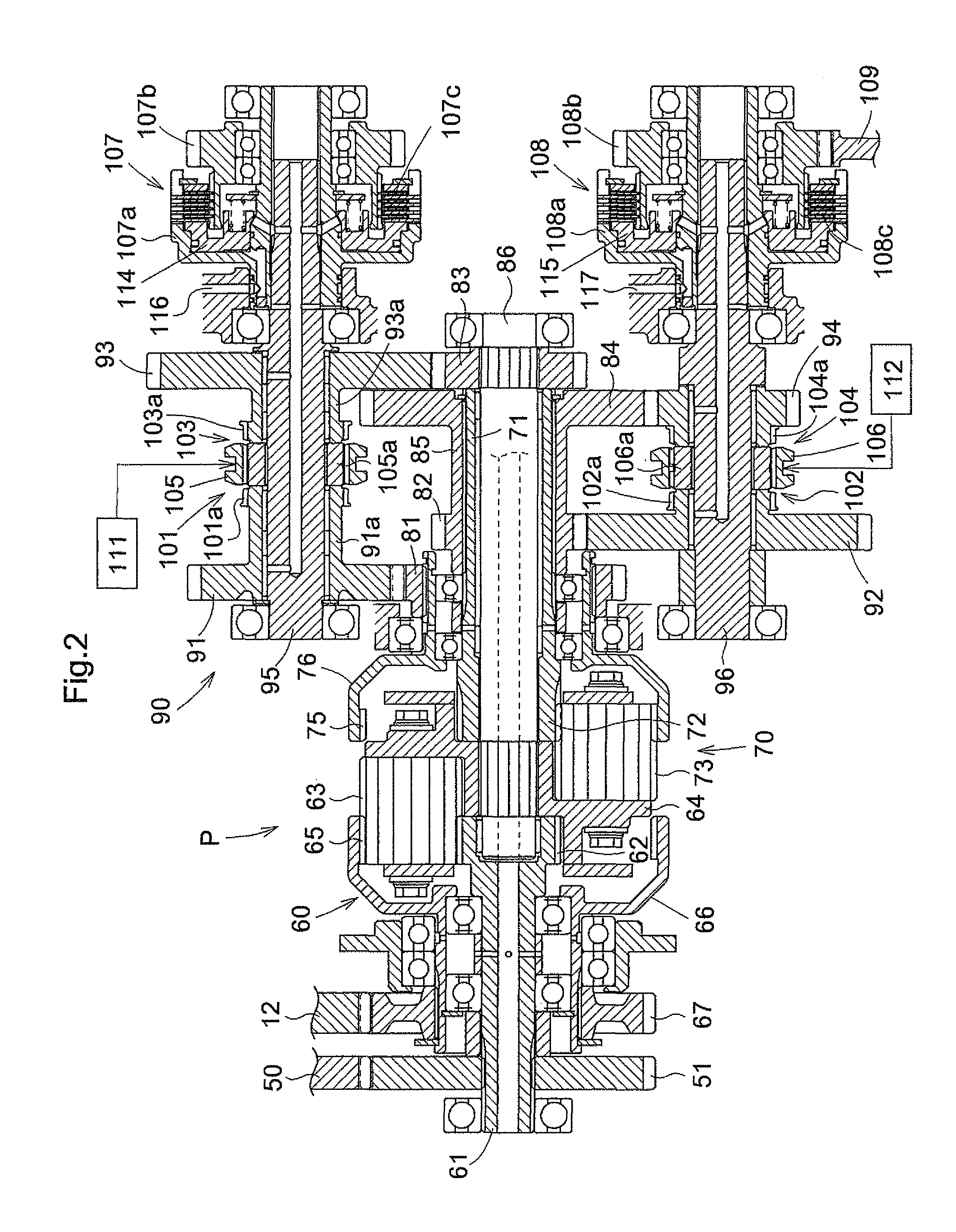
[0085]As shown in FIG. 1, the speed change transmission system A in this invention includes, besides the input shaft 22 and output shaft 30, the stepless transmission 20, the planetary transmission device P having a sun gear shaft 61 interlocked to a motor shaft 23 of the stepless transmission 20 through a gear 50 and a gear 51, and a speed range setter 90 having a first input gear 91 meshed with a first output gear 81 of the planetary transmission device P.
[0086]As shown in FIG. 1, the stepless transmission 20 includes a hydraulic pump 24 of the axial plunger type and variable displacement type having the input shaft 22 as a pump shaft (the input shaft being hereinafter called the pump shaft 22), and a hydraulic motor 25 of the axial plunger type driven by pressure oil from the hydraulic pump 24. The hydraulic motor 25 has the motor shaft 23.
[0087]That is, the stepless transmission 20 is a hydrostatic stepless transmission switchable to a forward rotational transmission state, a ne...
second embodiment
[0145]FIG. 9 is a line map of a traveling transmission system of a tractor equipped with a speed change transmission system A in this invention.
[0146]In the traveling transmission system of the tractor equipped with the speed change transmission system A in the second embodiment of this invention, output from output shaft 30 acting as output rotary member of the speed change transmission system A to a rear wheel differential mechanism 32 and a front wheel change speed device 40 through a forward and backward changeover device 10.
[0147]As shown in FIGS. 9, 10 and 11, the forward and backward changeover device 10 includes an input side rotary member 13 mounted on the output shaft 30 to be rotatable together, output gears 19a and 19b located at the front and rear of this input side rotary member 13, a forward drive friction clutch 14 mounted between one end of the input side rotary member 13 and the front output gear 19a, a backward drive friction clutch 16 mounted between the other en...
third embodiment
[0157]FIG. 12 is a line map of a traveling transmission system of a tractor equipped with a speed change transmission system A in this invention.
[0158]In the traveling transmission system of the tractor equipped with the speed change transmission system A in the third embodiment of this invention, output from output shaft 30 acting as output rotary member of the speed change transmission system A to a rear wheel differential mechanism 32 and a front wheel change speed device 40 through a forward and backward changeover device 10.
[0159]As shown in FIGS. 12, 13 and 14, the forward and backward changeover device 10 in the traveling transmission system equipped with the speed change transmission system A in the third embodiment has the same construction as the forward and backward changeover device 10 in the traveling transmission system equipped with the speed change transmission system A in the second embodiment.
[0160]When the speed change transmission system A in the third embodiment...
PUM
 Abstract
Description
Claims
Application Information
 - R&D
- Intellectual Property
- Life Sciences
- Materials
- Tech Scout
- Unparalleled Data Quality
- Higher Quality Content
- 60% Fewer Hallucinations
Browse by: Latest US Patents, China's latest patents, Technical Efficacy Thesaurus, Application Domain, Technology Topic, Popular Technical Reports.
© 2025 PatSnap. All rights reserved.Legal|Privacy policy|Modern Slavery Act Transparency Statement|Sitemap|About US| Contact US: help@patsnap.com


