Electronic blood pressure measurement device calculating blood pressure value

a blood pressure measurement and electronic technology, applied in the field of electronic blood pressure measurement devices, can solve the problems of reducing affecting so as to achieve the softness of the measurement site, improve the accuracy of blood pressure measurement, and improve the accuracy of blood pressure calculation.

Active Publication Date: 2012-11-13
OMRON HEALTHCARE CO LTD
View PDF23 Cites 10 Cited by
  • Summary
  • Abstract
  • Description
  • Claims
  • Application Information

AI Technical Summary

Benefits of technology

[0041]The present invention is based on a configuration in which a measurement bladder having a predetermined amount of air always sealed, i.e. having a predetermined volume, is squeezed by the squeezing portion at the measurement site. Accordingly, the volumetric change with respect to change in internal pressure indicated by the cuff compliance property of the measurement bladder is substantially constant (not readily altered), independent of the measurement state (softness of the measurement site, size in association with wrapping the measurement bladder around the measurement site, way of wrapping the measurement bladder, and the like). By changing the externally applied pressure to the measurement bladder in which a predetermined amount of air is sealed without drawing in / out air during blood pressure measurement, the amplitude of the pressure pulse wave detected at the measurement site by the pulse wave detection portion is corrected based on the obtained cuff compliance property.
[0042]By this correction, the inclusion of artifacts other than blood pressure information (volumetric change of measurement bladder) caused by the difference in the wrapping way of the measurement bladder around the measurement site (tightly wrapped / loosely wrapped), the size in association with the wrapping around the measurement site, softness of the measurement site, and the like, into the pulse wave amplitude can be avoided, allowing more accurate calculation of the blood pressure.

Problems solved by technology

Variation in the conveyance sensitivity of the volumetric change of the artery corresponding to the cuff pressure will cause reduction in the accuracy of the blood pressure measurement.
Therefore, distortion occurs in the pulse wave envelope corresponding to a series of such pulse wave signals.
Thus, the different cuff compliance ratio between a soft arm and a firm arm according to the cuff pressure will cause the pressure pulse wave amplitude to be distorted.
Thus, the accuracy of blood pressure measurement will be degraded due to the wrapping state.

Method used


Image

  • Electronic blood pressure measurement device calculating blood pressure value
  • Electronic blood pressure measurement device calculating blood pressure value
  • Electronic blood pressure measurement device calculating blood pressure value

Examples


first embodiment

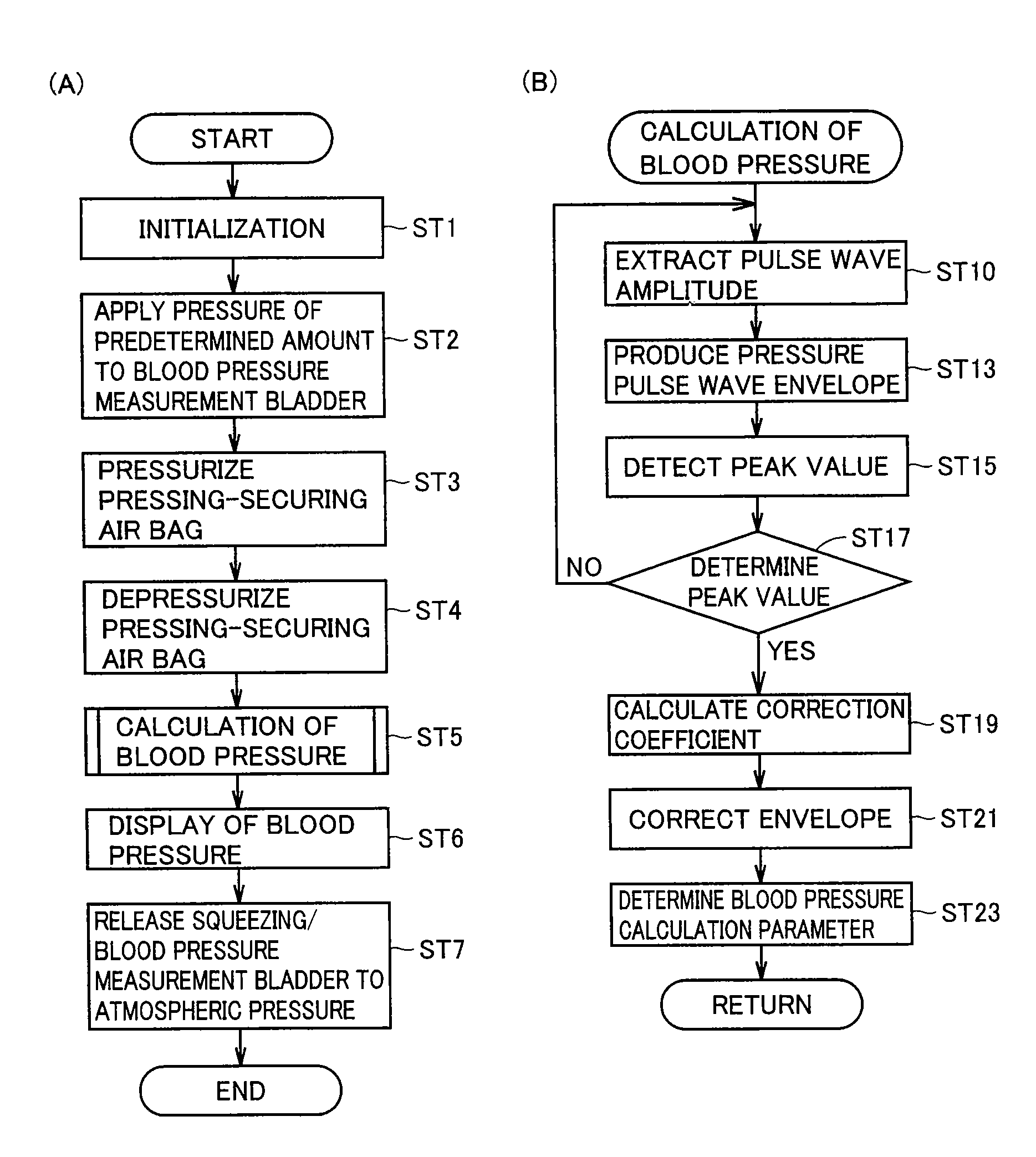
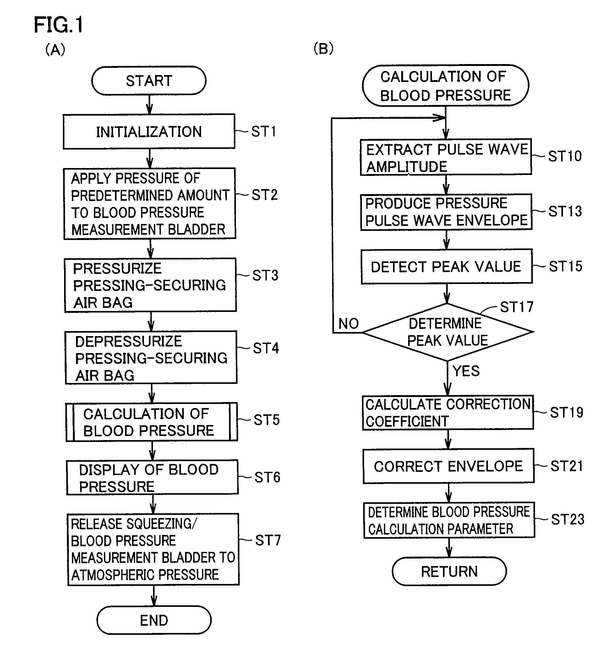
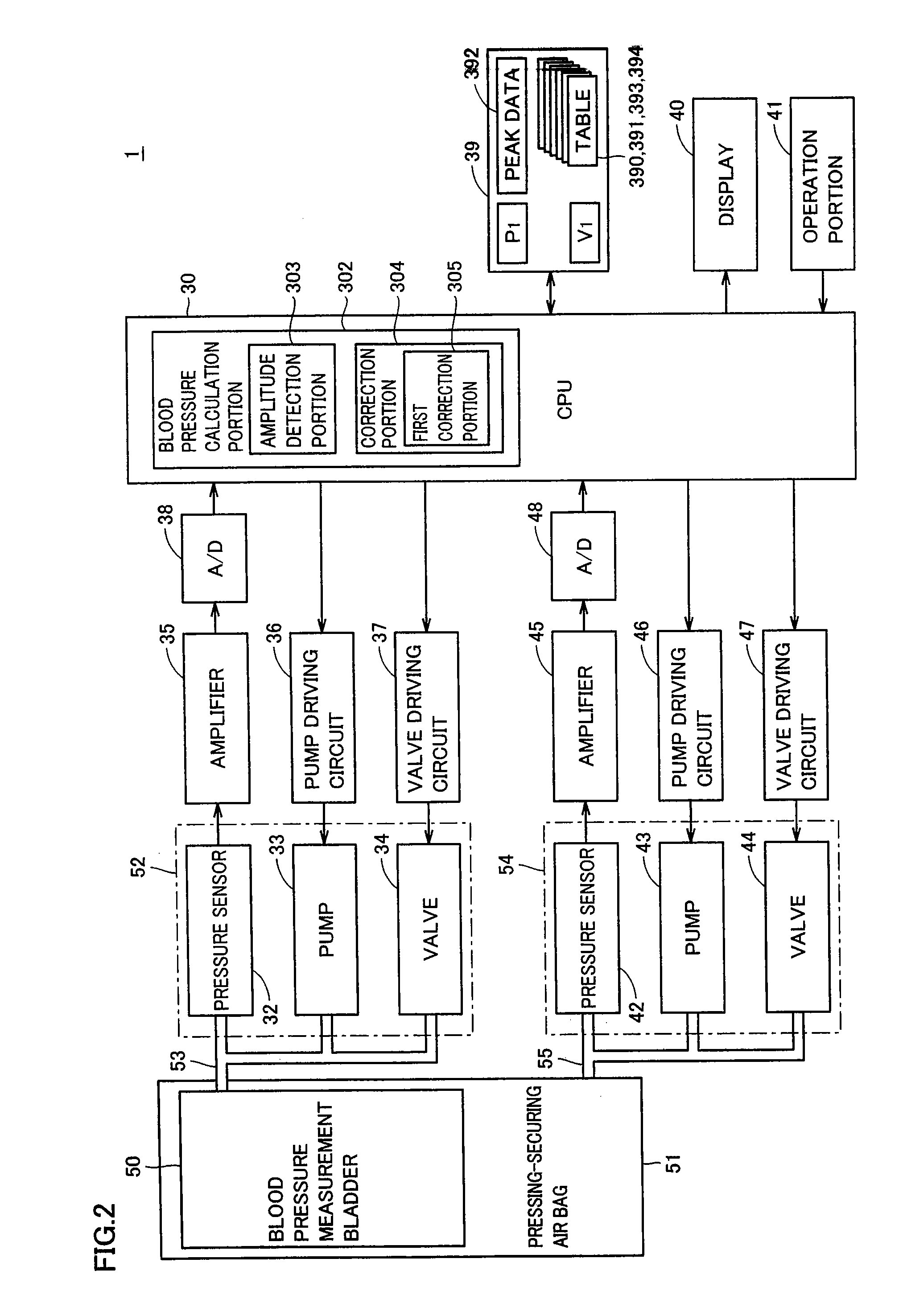
[0065]FIG. 1 represents a blood pressure measurement flow chart according to the first embodiment. FIG. 2 represents a block configuration of the electronic blood pressure measurement device of the first embodiment; FIG. 3 represents the air system of the electronic blood pressure measurement device of the first embodiment; and FIG. 4 schematically shows an appearance of the electronic blood pressure measurement device of the first embodiment and a state of usage for blood pressure measurement.

[0066](Device Configuration)

[0067]Referring to FIG. 2, an electronic blood pressure measurement device 1 includes a blood pressure measurement bladder 50, a pressing-securing air bag 51, a blood measurement air system 52 to supply or discharge air to or from blood pressure measurement bladder 50 via a tube (air tube) 53, an amplifier 35, a pump driving circuit 36, a valve driving circuit 37, and an A / D (Analog / Digital) converter 38, provided in association with blood pressure measurement air s...

second embodiment

[0124]The previous first embodiment employs a pressing-securing air bag 51 for wrapping blood pressure measurement bladder 50 around the measurement site. Alternatively, the tension of a belt may be employed as in the second embodiment, instead of the inflation / deflation of pressing-securing air bag 51.

[0125]The functional configuration of an electronic blood pressure measurement device 2 of the second embodiment is shown in FIG. 11. The process flow chart of blood pressure measurement is shown in FIG. 12. The wrapping structure is schematically shown in FIG. 13. Referring to these figures, the difference between electronic blood pressure measurement device 2 of FIG. 11 and electronic blood pressure measurement device 1 of FIG. 2 is set forth below. Specifically, electronic blood pressure measurement device 2 includes a reel squeeze portion 97 instead of pressing-securing air bag 51 of FIG. 2, a CPU 301 instead of CPU 30, as well as a squeeze fixture portion 95 and a motor driving c...


PUM


Abstract

A blood pressure measurement bladder (50) has a predetermined amount of air introduced and sealed therein. A CPU (30) measures in advance the P-V property. The blood pressure measurement bladder (50) is wrapped around a measurement site. By exerting pressure from the outer side to the blood pressure measurement bladder (50), the internal pressure in the blood pressure measurement bladder (50) is increased to exert pressure on the blood vessel. During this process, the cuff pressure in the blood pressure measurement bladder (50) generated by volumetric change of the blood vessel by changing the pressure exerted from the outer side to the blood pressure measurement bladder (50), and the pressure pulse wave data are detected. By adding the cuff compliance property obtained by the P-V property that was measured in advance to the detected data as a correction value of the pressure pulse wave, blood pressure is calculated.

Description

TECHNICAL FIELD[0001]The present invention relates to an electronic blood pressure measurement device for measuring blood pressure by pressing a measurement site such as the upper arm of a living body with a bladder, particularly to an electronic blood pressure measurement device for calculating a blood pressure value according to change in internal pressure in the bladder that occurs based on volumetric change of the blood vessel pressed through the bladder.BACKGROUND ART[0002]Conventionally, an electronic blood pressure measurement device employing the oscillometric method is provided. At this electronic blood pressure measurement device, the internal pressure in a bladder located in a cuff (hereinafter, referred to as cuff pressure) wrapped around a measurement site identified as a portion of a living body is adjusted for calculation of a blood pressure value according to change in internal pressure in the bladder that occurs based on volumetric change of the blood vessel that is...

Claims


Application Information

Patent Timeline
Patent Type & Authority Patents(United States)
IPC IPC(8): A61B5/02
CPCA61B5/02141A61B5/02233A61B5/02225A61B5/022A61B5/02
Inventor SANO, YOSHIHIKOTAKAHASHI, AKIHISAYAMASHITA, SHINGOSAWANOI, YUKIYA
Owner OMRON HEALTHCARE CO LTD
Why Eureka
Try Eureka