Control apparatus for vehicular power transmitting system

a control apparatus and transmission system technology, applied in the direction of electric devices, process and machine control, instruments, etc., can solve the problems of insufficient electric energy generated by the first electric motor, small electric energy consumption of the second electric motor, and large amount of electric energy to be stored, so as to reduce the electric efficiency and reduce the above-indicated electric efficiency , the effect of minimizing the degree of fuel economy reduction

Active Publication Date: 2012-11-13
TOYOTA JIDOSHA KK
View PDF21 Cites 10 Cited by
  • Summary
  • Abstract
  • Description
  • Claims
  • Application Information

AI Technical Summary

Benefits of technology

[0009]Upon starting of the vehicle, for example, however, the operating speed of the second electric motor operatively connected to the above-indicated drive wheels is zero or low according to the vehicle running speed, so that the amount of consumption of the electric energy by the second electric motor is small. Thus, the amount of electric energy generated by the first electric motor is not sufficiently, consumed when the amount of electric energy to be stored in the electric-energy storage device is restricted. Therefore, there is still a possibility of failure to ensure sufficient vehicle starting performance. In addition, the amount of electric energy generated by the first electric motor may further increase as a result of an increase of a drive torque produced by the engine and second electric motor in an uphill or other high-load running of the vehicle, which requires a drive force larger than in a flat-road running of the vehicle.

Problems solved by technology

Upon starting of the vehicle, for example, however, the operating speed of the second electric motor operatively connected to the above-indicated drive wheels is zero or low according to the vehicle running speed, so that the amount of consumption of the electric energy by the second electric motor is small.
Thus, the amount of electric energy generated by the first electric motor is not sufficiently, consumed when the amount of electric energy to be stored in the electric-energy storage device is restricted.
Therefore, there is still a possibility of failure to ensure sufficient vehicle starting performance.

Method used


Image

  • Control apparatus for vehicular power transmitting system
  • Control apparatus for vehicular power transmitting system
  • Control apparatus for vehicular power transmitting system

Examples


embodiment 1

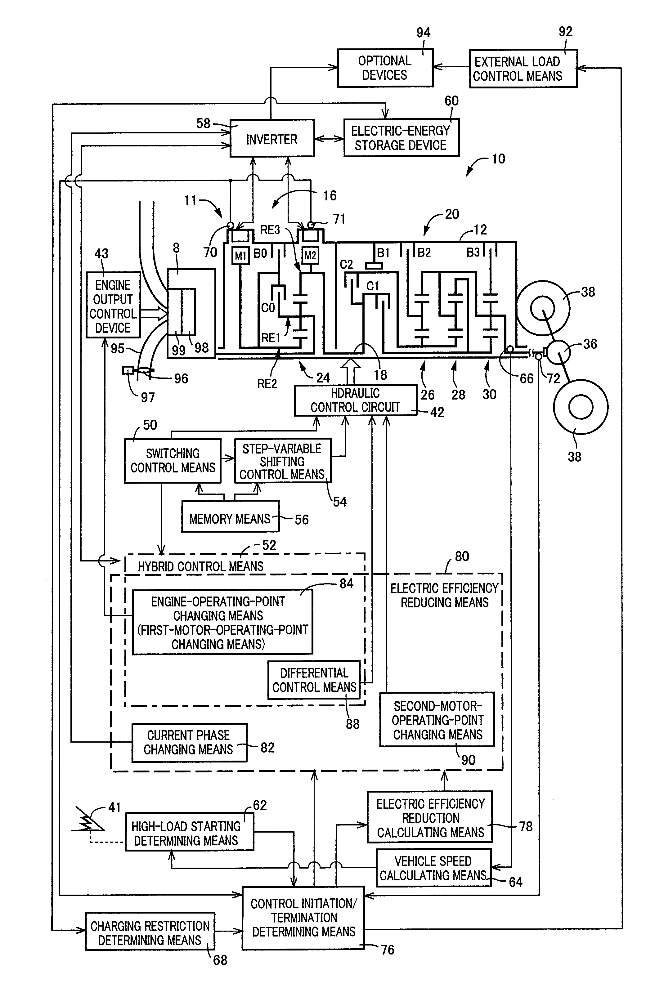
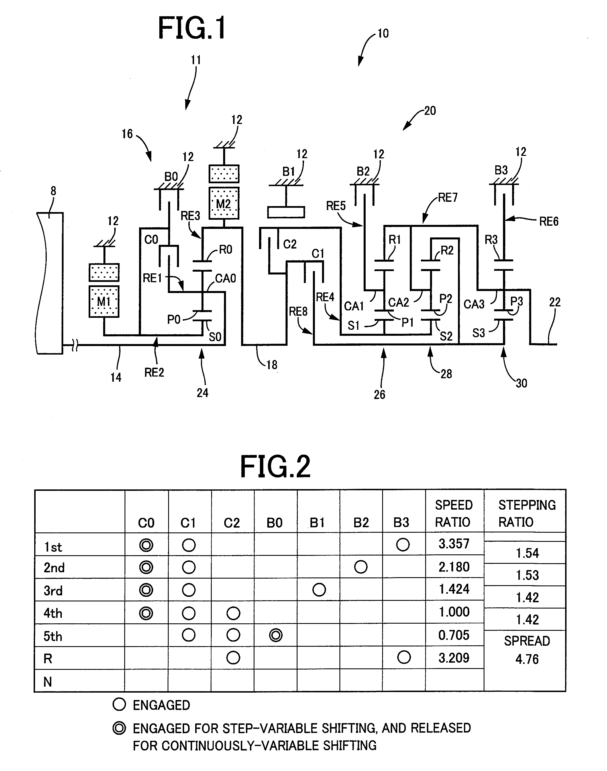
[0059]A control apparatus according to the present invention is used for a hybrid vehicle, for example. FIG. 1 is a schematic view for explaining a vehicular power transmitting system 10 (hereinafter referred to as “power transmitting system 10”) controlled by the control apparatus of the invention. In FIG. 1, the power transmitting system 10 includes: an input rotary member in the form of an input shaft 14; a differential portion 11 connected to the input shaft 14 either directly, or directly via a pulsation absorbing damper (vibration damping device) not shown; an automatic transmission portion (transmission portion) 20 disposed in a power transmitting path between the differential portion 11 and drive wheels 38 (shown in FIG. 6) of the vehicle, and connected in series via a power transmitting member (power transmitting shaft) 18 to the differential portion 11 and the drive wheels 38; and an output rotary member in the form of an output shaft 22 connected to the automatic transmis...

embodiment 2

[0161]FIG. 15 is a schematic view for explaining an arrangement of a vehicular power transmitting system 110 (hereinafter referred to as “power transmitting system 110”) according to another embodiment of the invention, and FIG. 16 is a table indicating shifting actions of the power transmitting system 110, in relation to different combinations of the operating states of hydraulically operated frictional coupling devices to effect the respective shifting actions, while FIG. 17 is a collinear chart for explaining the shifting actions of the power transmitting system 110.

[0162]The power transmitting system 110 in FIG. 15 controlled by the control apparatus according to the present invention includes the differential portion 11 having the first electric motor M1, power distributing mechanism 16 and second electric motor M2, and further includes an automatic transmission portion 112 which is disposed between the differential portion 11 and the output shaft 22 and connected in series to ...


PUM


Abstract

A vehicular power transmitting system, which permits the power transmitting system to provide a sufficient vehicle drive force even when an input of an electric energy into an electric-energy storage device is restricted and which reduces the electric efficiency of at least one of an first electric motor and a second electric motor, when an input of an electric energy into a chargeable electric-energy storage device is restricted, during an operation of an engine. This provides a vehicle drive force and generation of the electric energy by at least one of the first electric motor and the second electric motor, so that the amount of electric energy generated by the first electric motor is reduced, and / or the amount of electric energy consumed by the second electric motor is increased, whereby a sufficient vehicle drive force can be obtained even when the input into the electric-energy storage device is restricted.

Description

[0001]This application is a National Stage of International Application No. PCT / JP2008 / 072995 filed Dec. 17, 2008, the contents of all of which are incorporated herein by reference in their entirety.TECHNICAL FIELD[0002]The present invention relates to a control apparatus for a vehicular power transmitting system, and more particularly to a control apparatus which permits the vehicular power transmitting system to provide a sufficient drive force when a vehicle is required to run with a large drive force.BACKGROUND ART[0003]There is known a vehicular power transmitting system including an electrically controlled differential portion having a differential mechanism connected to a power transmitting path between an engine and a vehicle drive wheels, and a first electric motor which is operatively connected to the differential mechanism and an operating state of which is controlled to control a differential state of the differential mechanism, and further including a second electric mo...

Claims


Application Information

Patent Timeline
Patent Type & Authority Patents(United States)
IPC IPC(8): B60L15/20B60K1/00B60L50/16
CPCB60K6/445B60K6/547B60L3/0061B60L11/123B60L11/14B60L15/20B60L15/2054B60W10/08B60K6/365B60K1/02Y02T10/7275B60L2240/36B60W20/00B60W2510/244Y02T10/6217Y02T10/6239Y02T10/7077B60L50/16B60L50/61Y02T10/62Y02T10/64Y02T10/70Y02T10/7072Y02T10/72B60W20/30
Inventor IMAI, KEITAMATSUBARA, TOORUKUMAZAKI, KENTAIMAMURA, TATSUYATABATA, ATSUSHI
Owner TOYOTA JIDOSHA KK
Why Eureka
Try Eureka