
Intervertebral fusion device and method of use

a fusion device and vertebral technology, applied in the direction of internal osteosynthesis, osteosynthesis devices, prosthesis, etc., can solve the problems of structural integrity, lost productivity, and often failed approaches, and achieve the effect of enhancing stability and enhancing progressive solid bone fusion

Inactive Publication Date: 2012-11-20
SPINELOGIK
View PDF157 Cites 99 Cited by
  • Summary
  • Abstract
  • Description
  • Claims
  • Application Information

AI Technical Summary

Benefits of technology

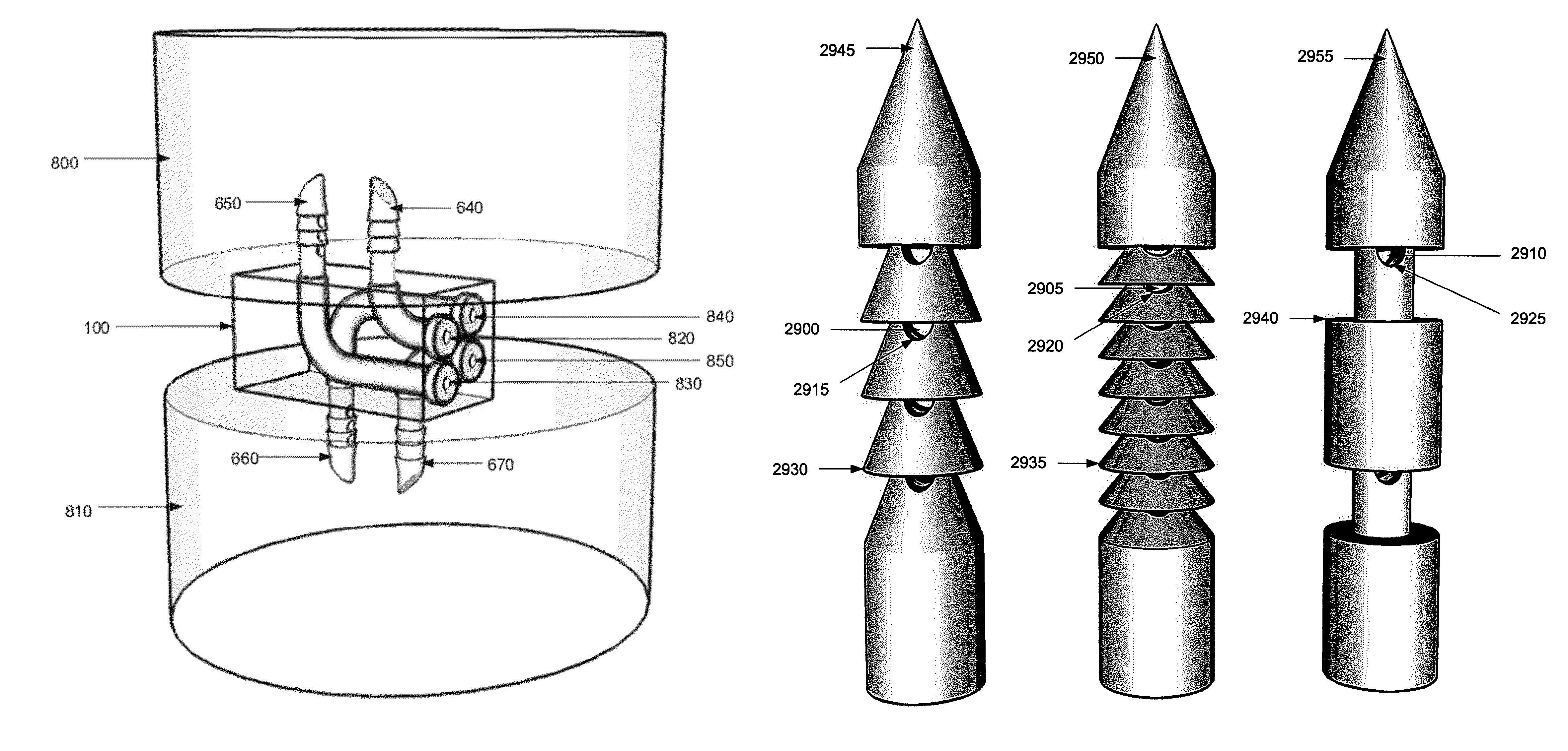
[0009]In some embodiments, the segments of the needles comprising these contours (e.g., angled teeth and backfacing ridges) have a diameter or circumference that is less than or equal to the diameter or circumference of proximal or distal needle segments. This allows the needle to pass through the fusion member's channel and into the bone readily (i.e., into the adjacent vertebral body).
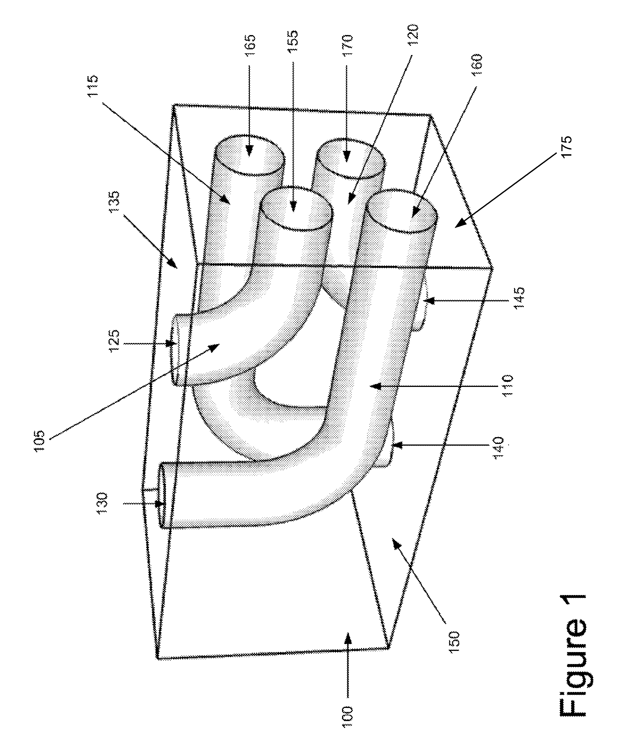
[0011]The fusion member may be composed of any number of materials, such as metals (including stainless steel, titanium, or nitinol), various polymers (including PMMA or polyetheretherketone), carbon fiber, etc. In some embodiments, the fusion member is partially or completely made of bioabsorbable or biodegradable materials, so that it can partially or completely be absorbed. In some instances, the fusion member's faces that are in contact with the vertebral endplates may have ridges or other surface contouring to enhance stability. The fusion member may comprise additional channels or cavities to be packed with bone graft material or bone graft substitutes to enhance progressive solid bony fusion. The fusion member may also be coated with or partially composed of human morphogenetic protein or other bone-inducing substances.

Problems solved by technology

Back and neck pain are the leading causes of disability and lost productivity for American workers under the age of 45.
This approach often failed due to inadequate structural integrity.
Despite these advancements, failure rates for spinal fusion surgeries remain unacceptably high, greater than 10 percent in most series.

Method used


Image

  • Intervertebral fusion device and method of use
  • Intervertebral fusion device and method of use
  • Intervertebral fusion device and method of use

Examples


embodiment 1600

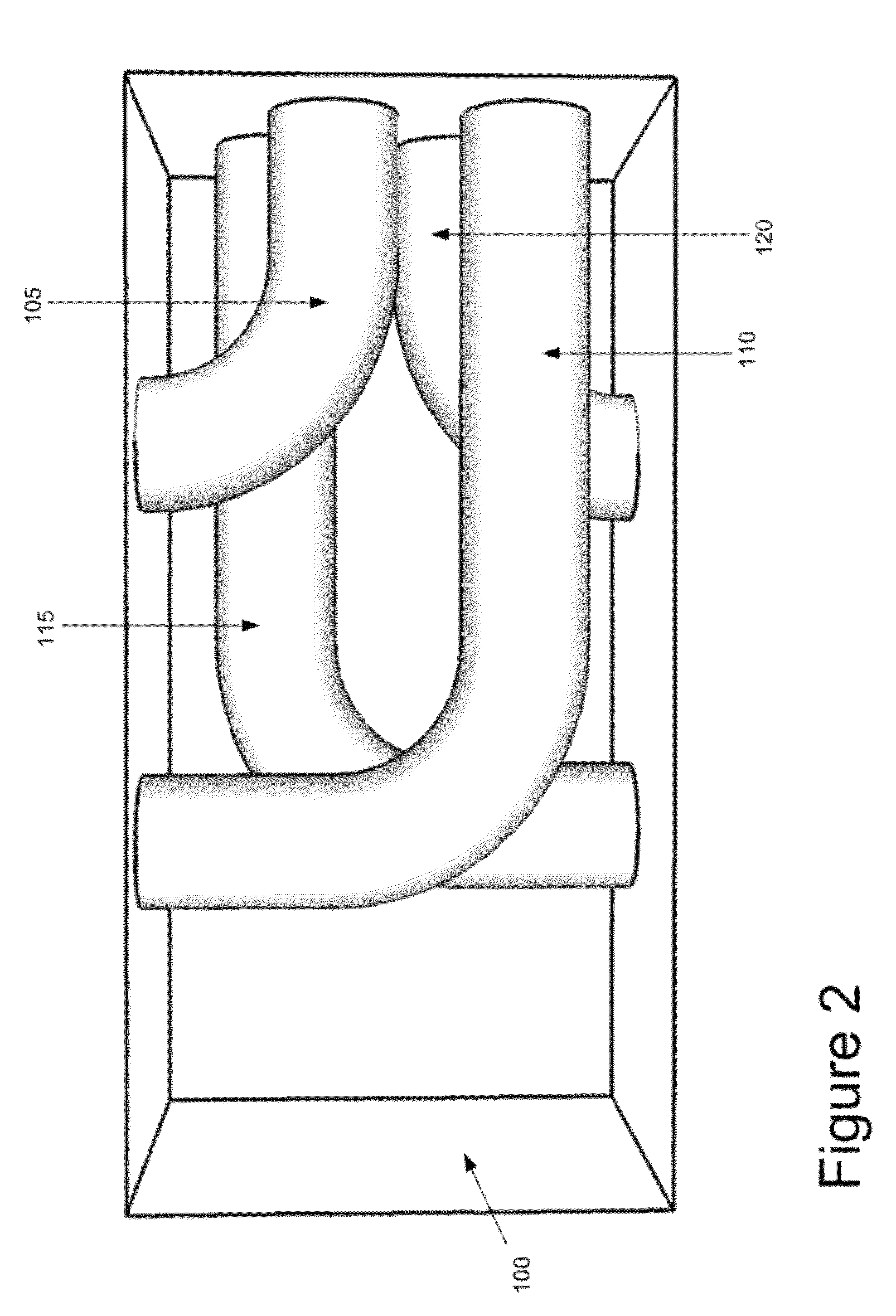
[0055]In FIGS. 16, 17, and 18, an alternate fusion member embodiment 1600 comprising two curved semicircular channels 1610 and 1620 is depicted with curved fusion needles 1630 and 1640 fully advanced through these channels into the marrow spaces of the vertebral bodies (not pictured) below and above the block. In FIG. 18, PMMA has been injected and formed collections 1800 and 1810 adjacent to the perforated, contoured tips of needles 1630 and 1640 within the marrow spaces of the adjacent vertebral bodies (not pictured).

[0056]B. Channels Traversing in all Three Dimensions

embodiment 1900

[0057]Another shape that the channels can take is to have a shape that traverses in x-, y-, and z-directions. FIGS. 19, 20, and 21 depict an alternate fusion member embodiment 1900 with nonparallel angled curved channels 1910 and 1920 and nonparallel angled curved channels 1930 and 1940 extending to inferior and superior block faces, respectively.

[0058]FIGS. 22 and 23 depict an alternate embodiment of a fusion member with channels that traverse in all three directions. As shown in these figures, the block 2200 includes two oblique channels 2210 and 2220 that are traversed by needles 2230 and 2240, which are rectangular in cross-sectional profile. The distal openings of these oblique, nonparallel channels 2210 and 2220 are located at or near the geometric centers of the inferior and superior block faces. FIG. 24 provides a detailed view of one fusion needle embodiment depicting the direct communication of the central needle lumen 2400 with perforations along the needle shaft as well ...


PUM

PropertyMeasurementUnit
outer diameteraaaaaaaaaa
flexibleaaaaaaaaaa
circumferenceaaaaaaaaaa

Abstract

Some embodiments of the invention disclose an apparatus for achieving rapid mechanical fusion between two adjacent vertebral bodies by positioning a fusion member with one or more channels between the two vertebral bodies. Once the fusion member properly positioned, one or more needles are passed through the fusion member's channels and advanced into the marrow space of the adjacent vertebral bodies. Each needle has a lumen for receiving adhesive material and supplying said material to the marrow space of the adjacent vertebral bodies. The adhesive material is for adhesively bonding the needle to the adjacent vertebral bodies. In some embodiments, a needle also has various surface contours along its shaft, including angled teeth and backfacing ridges.

Description

[0001]This Application claims benefit to U.S. Provisional Patent Application 61 / 040,136, entitled “Intervertebral Fusion Device and Method of Use”, filed Mar. 27, 2008.FIELD OF THE INVENTION[0002]The invention pertains to spinal implants and surgical procedures for spinal fusion and stabilization.BACKGROUND OF THE INVENTION[0003]Back and neck pain are the leading causes of disability and lost productivity for American workers under the age of 45. Degenerative disc disease and its sequelae, whereby the fibrocartilaginous disc between adjacent vertebral bodies loses height, hydration and structural integrity, is one of the most common causes of back and neck pain and may develop secondary to traumatic injuries, inflammatory processes or various degenerative disorders. When conservative treatment fails, surgical fusion of the vertebral segments across the abnormal disc may be the only currently available procedure for pain relief. An increasing number of these spinal fusions are perfor...

Claims


Application Information

Patent Timeline
Patent Type & Authority Patents(United States)
IPC IPC(8): A61F2/44
CPCA61F2/447A61F2/30723A61F2002/2817A61F2002/30062A61F2002/30092A61F2002/30261A61F2002/30271A61F2002/30448A61F2310/00976A61F2002/30331A61F2002/30354A61F2002/30357A61F2002/30779A61F2002/30787A61F2002/30841A61F2002/30881A61F2002/30904A61F2002/4631A61F2310/00017A61F2310/00023A61F2/30965A61B17/70A61F2002/30593
Inventor WENSEL, JEFFREY PARIS
Owner SPINELOGIK
Learn More