Precision pump having multiple heads and using an actuation fluid to pump one or more different process fluids

a technology of actuation fluid and process fluid, which is applied in the direction of liquid transferring device, positive displacement liquid engine, liquid fuel engine, etc., can solve the problems of less actuation mechanism in the factory, and undesirable sharing of a single actuation mechanism among multiple heads, etc., to save money and maintenance time, short dispense cycle, and fast and frequent switching between pump heads

Active Publication Date: 2012-11-27
TELEDYNE DIGITAL IMAGING US INC
View PDF46 Cites 21 Cited by
  • Summary
  • Abstract
  • Description
  • Claims
  • Application Information

AI Technical Summary

Benefits of technology

[0010]In contradiction to typical deployments of pumps in such applications, particularly those used for high-precision metering, an exemplary pump employing teachings of a preferred embodiment of the invention is capable of pumping more than one type of chemistry or process fluid without requiring cleaning or changing of surfaces contacting the processing fluid. The pump employs multiple pumping heads, each capable of handling a different type of manufacturing fluid. Multiple pumping heads share a common actuation mechanism. Although each pump might be larger when compared to a pump with a single head, utilizing fewer actuation mechanisms than pumping heads saves very valuable space in crowded processing facilities, such as those used for fabricating semiconductor components, which use a large number of pumps. Since actuation mechanisms are sometimes the most complex part of a pump, fewer actuation mechanism in a factory saves money and maintenance time.
[0011]Sharing a single actuation mechanism among multiple heads may seem undesirable, particularly for fluid metering applications. Having a shared actuation mechanism typically means that only one pumping head may be actuated at a time. However, in one embodiment the exemplary pump is capable of fast and frequent switching between pump heads. With actuation between pump heads capable of being switched quickly, there is little delay between demand for dispense and dispense in applications having very short dispense cycles due to relatively small amounts of fluid that are being dispensed.
[0028]A plurality of isolation valves may be used where each isolation valve is located between the actuating mechanism and one of the plurality of actuating fluid chambers for selectively preventing and allowing the flow of process fluid between the actuating mechanism and one or more selected actuating fluid chambers. Each isolation valve may be a proportional control valve to enable dispensing out of more than one pumping head simultaneously, at least one flow rate using a single one of the actuating mechanism.
[0030]A plurality of isolation valves may be provided where each isolation valve is located between the actuating mechanism and one of the plurality of actuating fluid chambers for selectively preventing and allowing the flow of process fluid between the actuating mechanism and one or more selected actuating fluid chambers. Each isolation valve may be a proportional control valve to enable dispensing out of more than one pumping head simultaneously, at least one flow rate using a single one of the actuating mechanism.
[0032]A plurality of isolation valves may be provided where each isolation valve is located between the actuating mechanism and one of the plurality of actuating fluid chambers for selectively preventing and allowing the flow of process fluid between the actuating mechanism and one or more selected actuating fluid chambers. Each isolation valve may be a proportional control valve to enable dispensing out of more than one pumping head simultaneously, at least one flow rate using a single one of the actuating mechanism.

Problems solved by technology

Although each pump might be larger when compared to a pump with a single head, utilizing fewer actuation mechanisms than pumping heads saves very valuable space in crowded processing facilities, such as those used for fabricating semiconductor components, which use a large number of pumps.
Since actuation mechanisms are sometimes the most complex part of a pump, fewer actuation mechanism in a factory saves money and maintenance time.
Sharing a single actuation mechanism among multiple heads may seem undesirable, particularly for fluid metering applications.

Method used


Image

  • Precision pump having multiple heads and using an actuation fluid to pump one or more different process fluids
  • Precision pump having multiple heads and using an actuation fluid to pump one or more different process fluids
  • Precision pump having multiple heads and using an actuation fluid to pump one or more different process fluids

Examples


Embodiment Construction

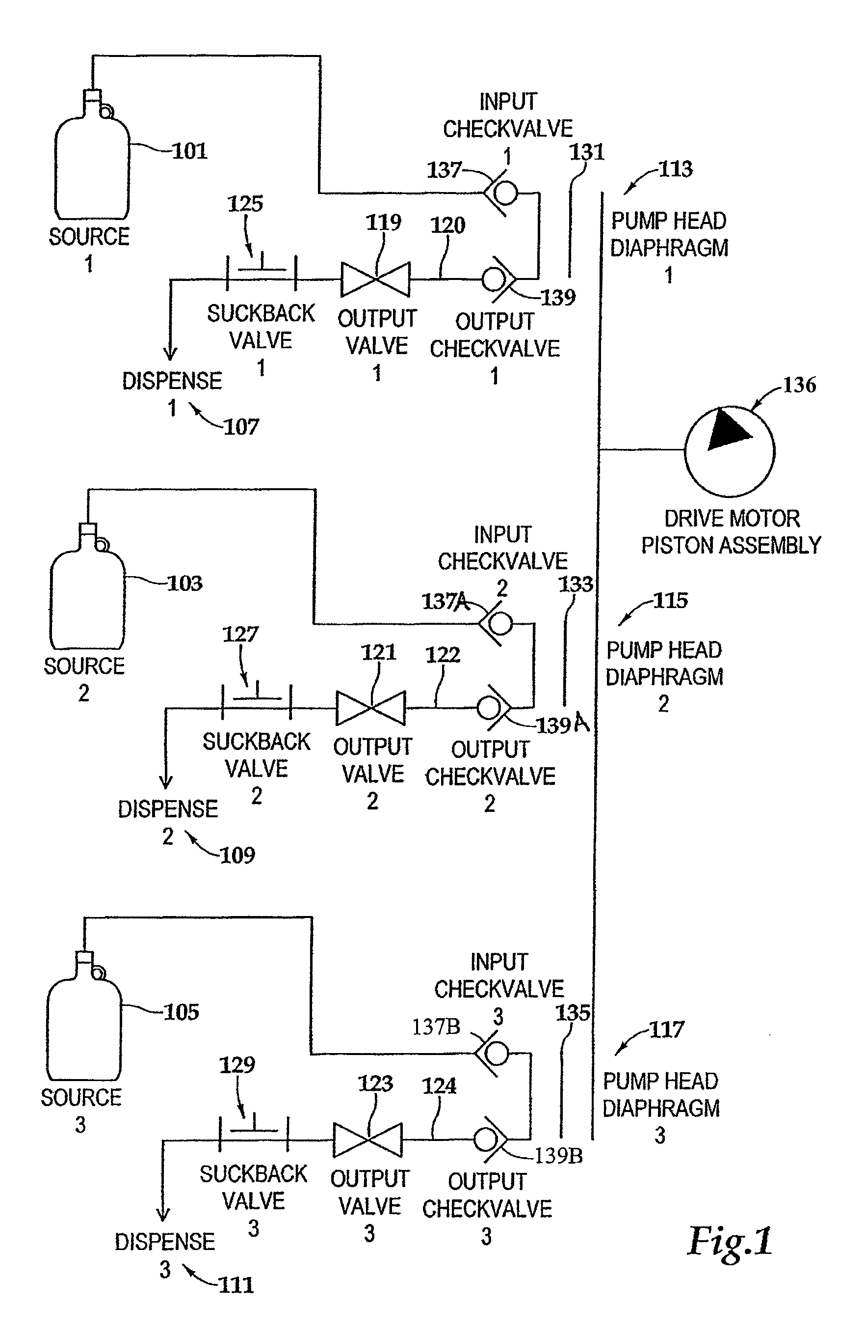
[0063]FIG. 1 schematically illustrates one example of a high precision, single stage, multiple head dispense pump for pumping a plurality of different chemicals in a high purity application. A pumping head is a portion of a pump that, among other possible functions, contacts and applies force to the process fluid in order to move it. In a high precision, multiple head pump, more than one pumping head is actuated by a common actuation mechanism. In the illustrated example, a multiple head pump is used to dispense chemicals or process fluids from three separate sources 101, 103 and 105 to each of three separate dispense points 107, 109 and 111, respectively. Each source and dispense point is coupled through a pump head 113, 115, or 117. Each pump head functions to move a predetermined amount of fluid from the source to the corresponding dispense point. Because each pump head functions independently and does not share with the other pump heads any surfaces that contact process fluids, ...


PUM


Abstract

A pump for one or more different process fluids is provided including a pumping chamber having a process fluid inlet and outlet coupled to a process fluid valve on each pumping chamber for selectively preventing and allowing flow of process fluid through the pumping chamber. An actuation mechanism for pumping actuating fluid to actuating fluid chambers is provided that is in communication with the actuating fluid chambers to permit flow into each actuating fluid chamber of incompressible actuating fluid. A diaphragm separates each pumping chamber from an associated actuating fluid chamber for separating process fluid from actuating fluid. The actuation mechanism is removable by a quick disconnect that provides for disconnection of the activation mechanism without affecting process fluid. Operation of the actuation mechanism to displace actuating fluid causes actuating fluid to flow only into each actuating fluid chamber having an opened process fluid valve, resulting in pumping.

Description

CROSS-REFERENCE TO RELATED APPLICATIONS[0001]This application is a continuation-in-part application of U.S. application Ser. No. 11 / 938,408, filed on Nov. 12, 2007, entitled Precision Pump with Multiple Heads which is a continuation-in-part application of U.S. application Ser. No. 11 / 778,002, filed on Jul. 13, 2007, entitled Precision Pump with Multiple HeadsFIELD OF THE INVENTION[0002]The present invention relates generally to apparatus used in metering fluids with high precision, particularly in fields such as semiconductor manufacturing.BACKGROUND OF THE INVENTION[0003]Many of the chemicals used in manufacturing integrated circuits, photomasks, and other devices with very small structures are corrosive, toxic and expensive. One example is photoresist, which is used in photolithographic processes. In such applications, both the rate and amount of a chemical in liquid phase—also referred to as process fluid or “chemistry”—that is dispensed onto a substrate must be very accurately c...

Claims


Application Information

Patent Timeline
Patent Type & Authority Patents(United States)
IPC IPC(8): F04B43/067B67D7/58
CPCF04B13/02F04B15/04F04B43/06F04B43/067F04B43/0736F04B53/20F04B53/10F04B43/02F04B45/04F04B53/16F04B49/065
Inventor LAESSLE, JOHNVINES, JOHNKIDD, BRIAN
Owner TELEDYNE DIGITAL IMAGING US INC
Why Eureka
Try Eureka