Simplified cleaning and filling device

a filling device and cleaning method technology, applied in the field of simple filling device, can solve the problems of long filling, inability to allow all the interstices of the cavity to be filled, residual air pockets remaining trapped, etc., and achieve the effect of simple method, low cost and little bulk

Active Publication Date: 2012-11-27
WEILL DAVID
View PDF21 Cites 31 Cited by
  • Summary
  • Abstract
  • Description
  • Claims
  • Application Information

AI Technical Summary

Benefits of technology

[0014]More precisely, the object of the invention is to propose a method and a device suitable for filling, cleaning, unblocking-type operations that make it possible to obtain a good result and in a short time.
[0016]An object of the invention consists in proposing a simple method and device, of little bulk and low cost.
[0017]The concept of the invention consists in subjecting the enclosure, within which the intervention is necessary, to cycles of sudden pressure releases, causing a particular motion of fluid, gaseous, liquid and even pasty, within the enclosure, which has the effect of cleaning, filling, unblocking the enclosure.
[0032]The method for difficult intervention in a closed enclosure may include a circulation of air within the duct so as to cause the pressure within the duct to be lowered by the Venturi effect.

Problems solved by technology

Such a method has the disadvantages of a lengthy filling if the volume is great, of not allowing a filling of all the interstices of the cavity and residual air pockets remaining trapped.
However, the proposed device has the disadvantage of being complex, of having a voluminous mechanism and of being difficult to apply and to control due to the particular operation of the pump.
Additionally, the solution does not make it possible to fully eliminate all the air pockets from the cavity and its filling and cleaning are insufficient.
However, such a solution requires two controlled pumping systems, relatively long ducts, many connections, depends on the inertia of the components in motion, the inertia of the columns of liquids in motion and is subjected to the various damping factors associated with the various components such as the ducts in the context of the pressure variations.
This solution relies therefore on a complex mechanism posing problems of reliability.
In addition, the energy consumed is considerable and this solution causes a considerable consumption of liquid.
Finally, it generates cavitation phenomena that are always accompanied by often undesirable violent effects and are not suitable for the envisaged uses.
This device has many disadvantages like those mentioned previously, to which the fact of using the rotor is added: specifically, this device requires particular connections between the ducts, causes losses of energy and wear by friction, problems of sealing and hygiene because the liquid passes through the rotor.
In practice, this method is limited in the case of stubborn blockages.

Method used


Image

  • Simplified cleaning and filling device
  • Simplified cleaning and filling device
  • Simplified cleaning and filling device

Examples


Embodiment Construction

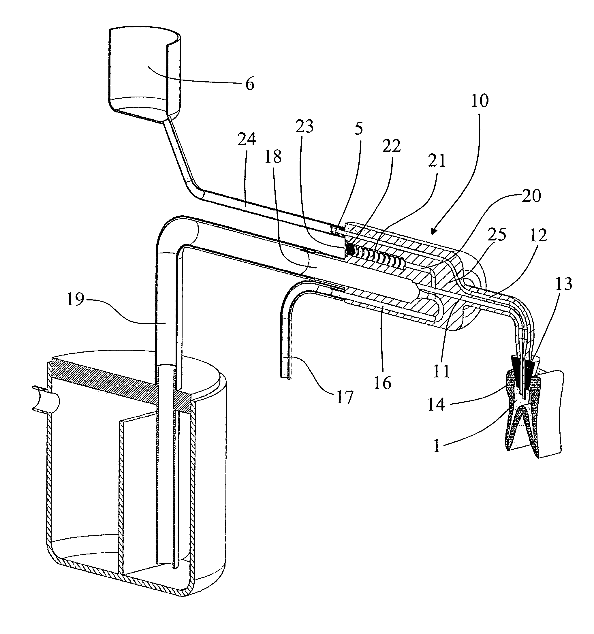
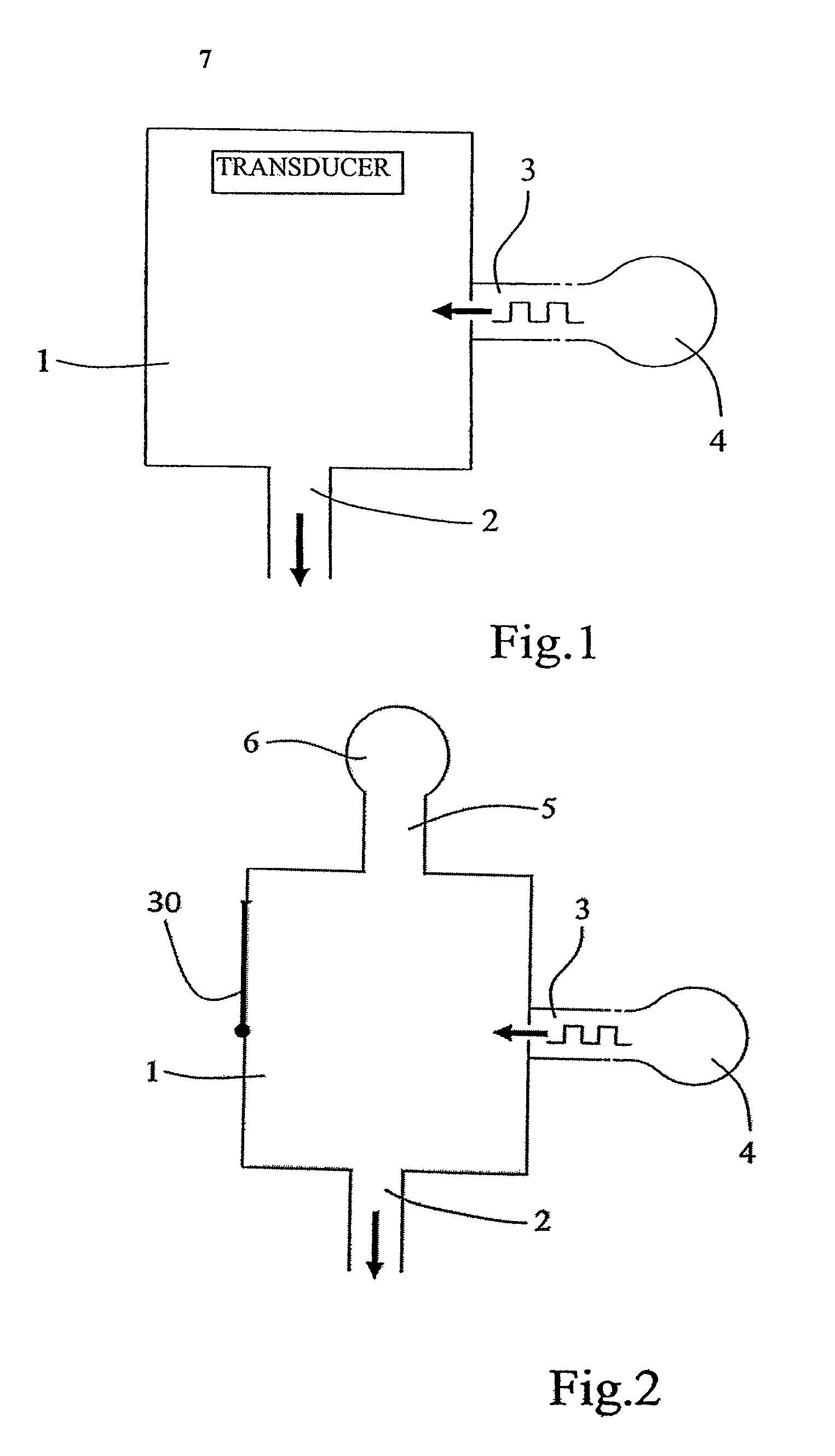
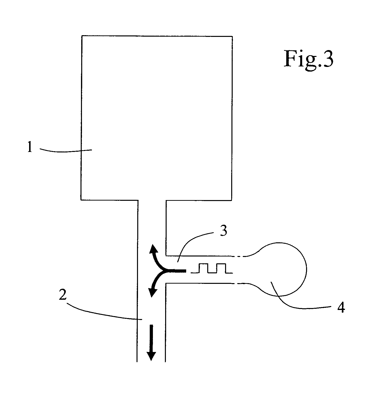
[0041]FIGS. 1 to 3 represent schematic devices illustrating the concept of the invention.

[0042]FIG. 1 illustrates a closed cavity 1 on which it is necessary to intervene, for a cleaning operation. The device according to the invention comprises a pressure reduction means 2 connected to the cavity via a first opening, this means being a pump in this embodiment, a means of sudden pressure release 3 connected to the enclosure 1 via a second opening, this means being a valve-type release device in this embodiment and this means being connected to a reservoir containing a fluid 4, air at atmospheric pressure in this embodiment.

[0043]For reasons of simplification, the cavity is represented schematically as rectangular. It could however have any complex form and particularly have hard-to-reach nooks.

[0044]The cleaning method of the invention, applied with the aid of the foregoing device, comprises the following essential steps:[0045]reduction of the pressure inside the enclosure 1 with the...


PUM

PropertyMeasurementUnit
pressureaaaaaaaaaa
lengthaaaaaaaaaa
thermalaaaaaaaaaa

Abstract

Device for difficult intervention in a closed enclosure, including a duct, a first end of which is intended to penetrate within the chamber, the duct being furthermore connected:to a pressure reduction device, the function of which is to lower the pressure within the enclosure;to an outlet duct for extracting the sucked-up material; andto a duct connected to a device for suddenly relieving the pressure and to an opening in the device for bringing the end of the duct into contact with the external air when the pressure within the enclosure reaches a value below a certain threshold.

Description

[0001]This application is a 371 of PCT / IB2005 / 001620 filed on Jun. 9, 2005, published on Jan. 26, 2006 under publication number WO 2006 / 008592 A1 which claims priority benefits from French Patent Application Number 04 / 06331 filed Jun. 11, 2004.[0002]The invention relates to a method and a device for a filling, cleaning, unblocking-type intervention in a closed or virtually closed enclosure. It is particularly suitable for complex-shaped and / or hard-to-reach cavities. It offers many applications including in construction, chemical or food production installations, medicine and dentistry.BACKGROUND OF THE INVENTION[0003]To clean a closed enclosure, it is known practice to make two openings in the enclosure in order to cause a fluid, gaseous or liquid, where necessary having chemical cleaning properties, to circulate therein at high pressure. This method rapidly reaches its limits:[0004]for certain complex shapes of the enclosure, walls remain unreachable by the fluid and uncleaned;[00...

Claims


Application Information

Patent Timeline
Patent Type & Authority Patents(United States)
IPC IPC(8): A61C17/00A61C17/02A61G17/02A61C5/02A61C5/04A61C5/40A61C5/50A61L12/02A61L12/08B08B7/02B08B9/00B08B9/02B08B9/08
CPCA61C5/02A61C5/04A61L12/02A61L12/08B08B9/08B08B9/00B08B9/0321B08B9/0325B08B7/02A61C5/40A61C5/50A61C17/022
Inventor WEILL, DAVID
Owner WEILL DAVID
Why Eureka
Try Eureka