
Systems and methods of identifying catheter malfunctions using pressure sensing

a technology of pressure sensing and catheter malfunction, which is applied in the direction of suction devices, other medical devices, medical preparations, etc., can solve the problems of catheter leakage, catheter obstruction or obstruction in such delivery systems, and catheters can also have and develop operational problems

Active Publication Date: 2012-11-27
MEDTRONIC INC
View PDF160 Cites 40 Cited by
  • Summary
  • Abstract
  • Description
  • Claims
  • Application Information

AI Technical Summary

Benefits of technology

The present invention provides methods and systems for identifying catheter malfunctions by analyzing changes in pressure in the delivery lumen of a catheter. The methods involve measuring decay time after a selected pulse, peak pressure within the delivery lumen after a selected pulse, and comparing the measured data to pre-defined values. The methods can be performed in real-time or at a later time for analysis. The invention can help to quickly detect and address catheter malfunctions, which can improve the efficiency and accuracy of catheter delivery and reduce the risk of complications.

Problems solved by technology

While perhaps the least complex, catheters can have and can develop operational problems.
Sometimes catheters in such delivery systems can become obstructed or clogged.
Catheters can also leak due to cuts, tears, etc.
A leak can result in a double problem.
In addition to the lack of therapeutic substance supplied to the delivery site of the patient, the therapeutic substance could be dispersed elsewhere in the body of the patient which may create further issues.
It has, however, been difficult to detect the malfunction of a catheter.
For example, if the catheter has a leakage, the implantable delivery device could continue to deliver therapeutic substance and there may be no way to know that the therapeutic substance was not reaching the desired delivery site.
The patient may not receive the benefit of the therapeutic substance but might not know why.
But it may be difficult to know why the failure occurred.
The failure to deliver might have been caused by other factors, such as power failure, pump failure, an empty reservoir, etc.

Method used


Image

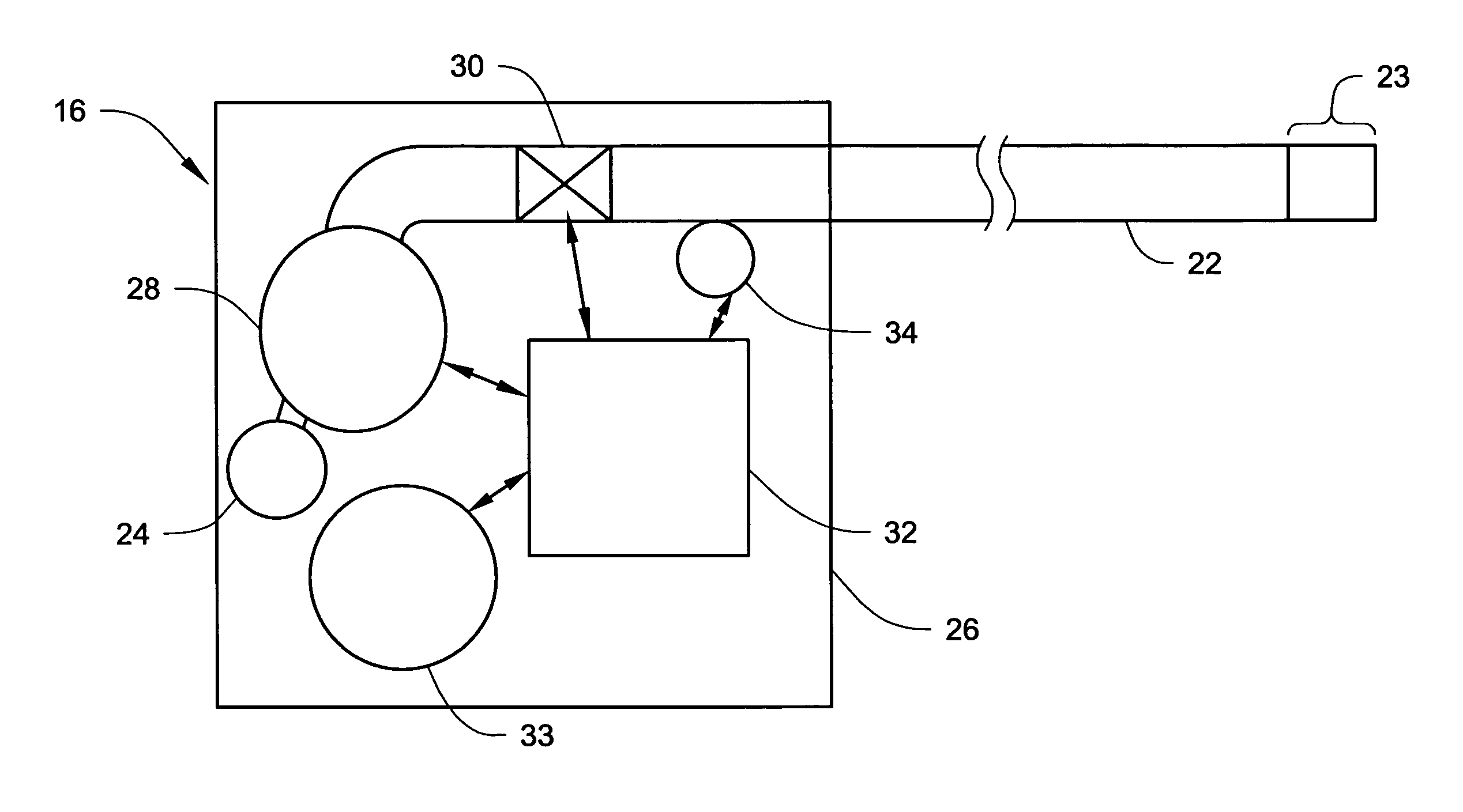
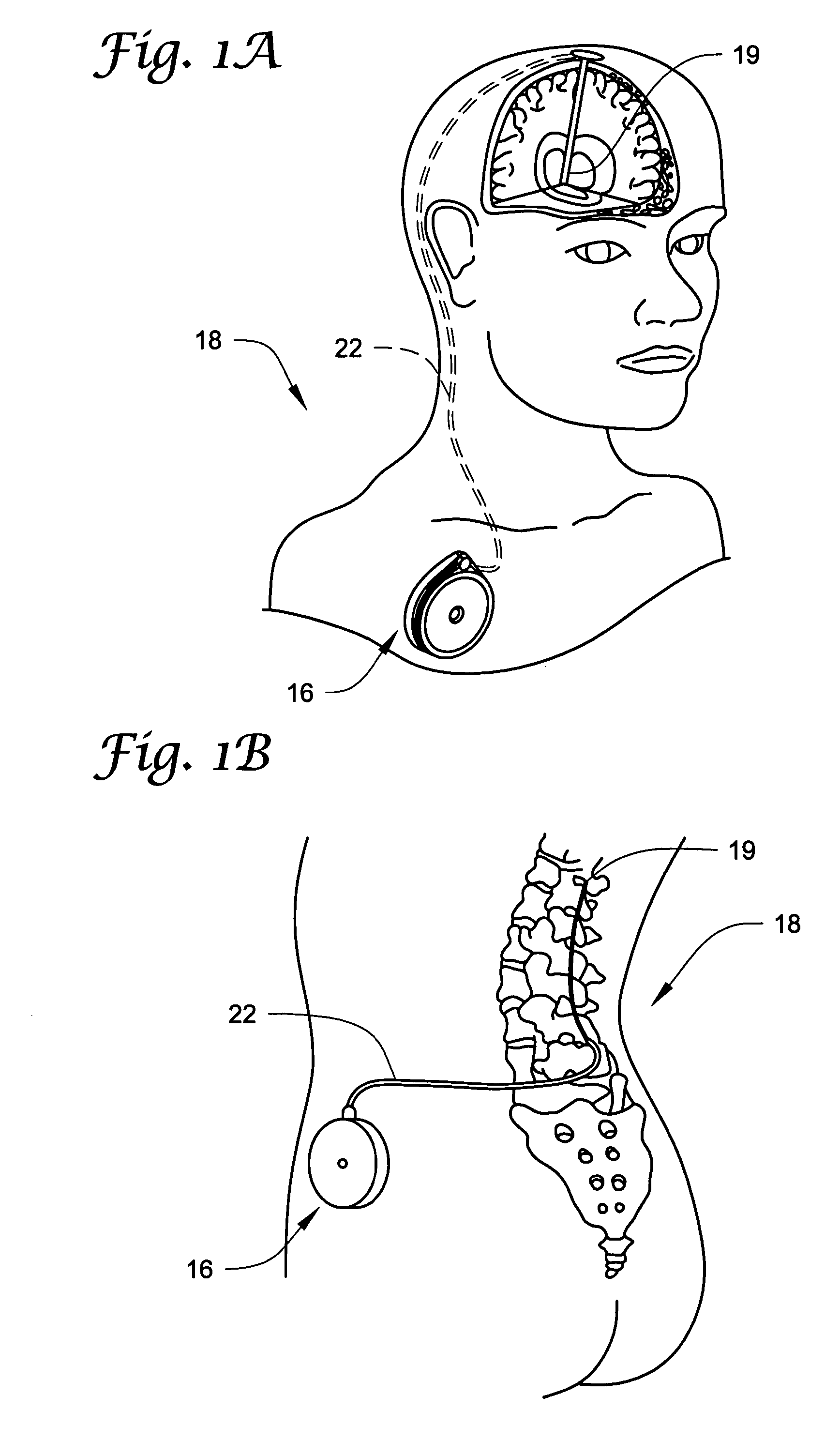
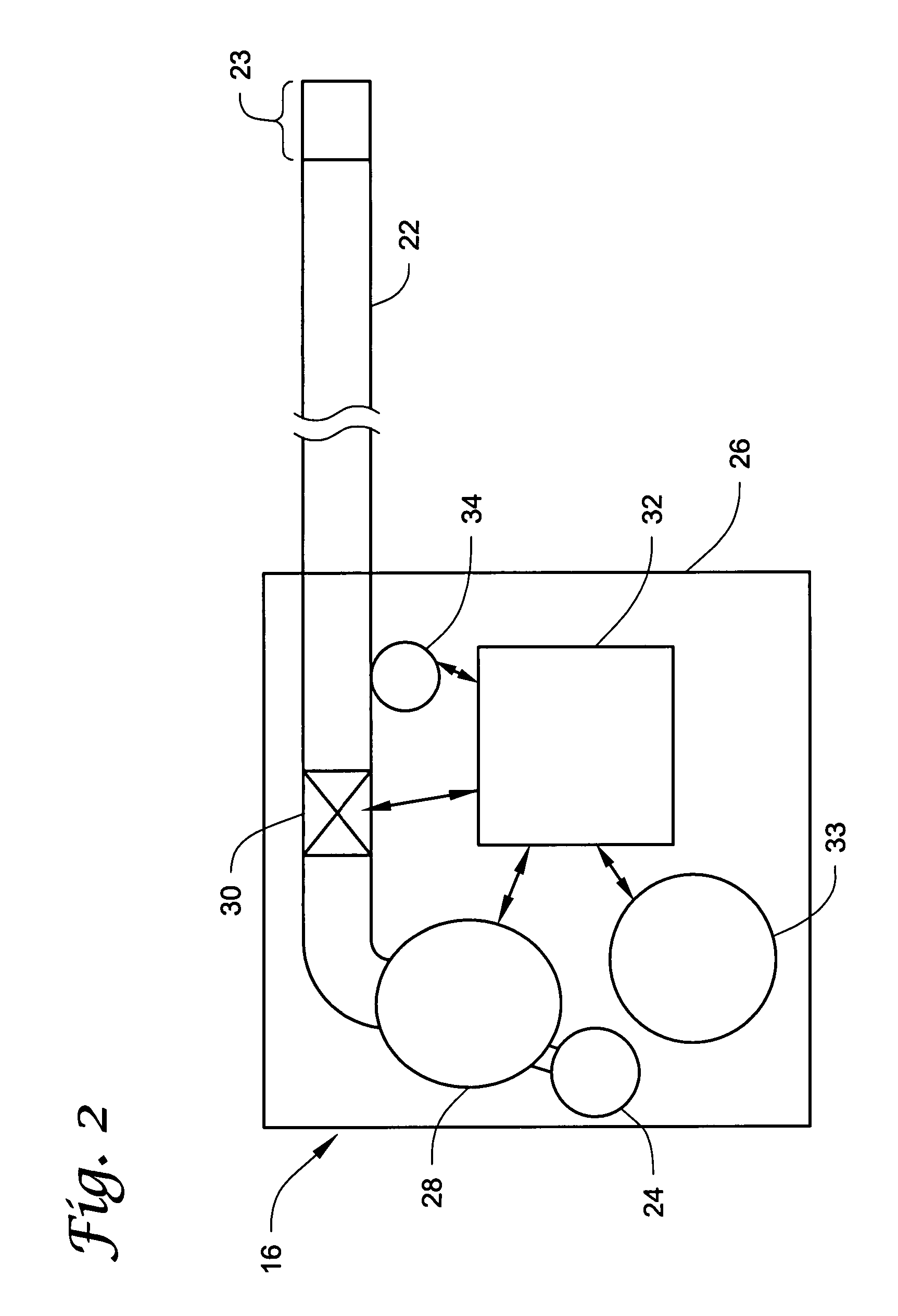
  • Systems and methods of identifying catheter malfunctions using pressure sensing
  • Systems and methods of identifying catheter malfunctions using pressure sensing
  • Systems and methods of identifying catheter malfunctions using pressure sensing

Examples


Embodiment Construction

[0035]In the following detailed description of illustrative embodiments of the invention, reference is made to the accompanying figures of the drawing which form a part hereof, and in which are shown, by way of illustration, specific embodiments in which the invention may be practiced. It is to be understood that other embodiments may be utilized and structural changes may be made without departing from the scope of the present invention.

[0036]It is noted that the terms “comprises” and variations thereof do not have a limiting meaning where these terms appear in the accompanying description and claims. Moreover, “a,”“an,”“the,”“at least one,” and “one or more” are used interchangeably herein.

[0037]Relative terms such as left, right, forward, rearward, top, bottom, side, upper, lower, horizontal, vertical, and the like may be used herein and, if so, are from the perspective observed in the particular figure. These terms are used only to simplify the description, however, and not to l...


PUM


Abstract

Methods and systems for determining whether a catheter malfunction is present in a catheter by analyzing changes in the pressure of fluids being pumped through the delivery lumen of the catheter. The pressure changes that may be monitored may include, e.g., the peak pressure within the catheter and / or the pressure decay profile. The catheter malfunctions that may be determined using the methods and systems of the invention may include, e.g., leaks, blockages, the presence of gas bubbles, etc.

Description

RELATED APPLICATION[0001]The present application claims the benefit under 35 U.S.C. Section 119(e) of U.S. Provisional Patent Application Ser. No. 60 / 789,729, filed Apr. 6, 2006 and titled SYSTEMS AND METHODS OF IDENTIFYING CATHETER MALFUNCTIONS USING PRESSURE SENSING, which is hereby incorporated by reference in its entirety.TECHNICAL FIELD[0002]The present invention relates generally to pressure sensing in implantable medical devices and, more particularly, to pressure sensing in implantable medical devices delivering a fluid to a patient and using the sensed pressure to determine the occurrence of malfunctions in the catheter.BACKGROUND[0003]Implantable drug delivery or infusion devices and / or systems are commonly used, for example when chronic administration of a pharmaceutically active agent or therapeutic substance to a patient is required. An implantable infusion pump-catheter delivery system may be preferred when it is important to deliver the agent to a specific site or whe...

Claims


Application Information

Patent Timeline
Patent Type & Authority Patents(United States)
IPC IPC(8): A61M31/00A61M37/00
CPCA61M5/14276A61M5/16859A61M2205/14A61M2205/15
Inventor MIESEL, KEITH A.PANKEN, ERIC J.
Owner MEDTRONIC INC
Learn More