Method for contacting large volumes of gas and liquid across microscopic interfaces

a microscopic interface and large volume technology, applied in the direction of liquid degasification, separation processes, carburetor air, etc., can solve the problems of large overall volume required to achieve contact conditions on a commercial scale, process limitation, and inability to arrange, etc., to achieve effective industrial scale utilization, reduce spatial separation, and optimize interphase transport efficiency

Inactive Publication Date: 2005-07-19
JAECO TECH
View PDF25 Cites 52 Cited by
  • Summary
  • Abstract
  • Description
  • Claims
  • Application Information

AI Technical Summary

Benefits of technology

[0031]The present invention provides a method of creating and maintaining beneficial physical conditions for the transport of momentum, heat, and mass between a liquid and a gas across a multitude of microscopically small gas bubble interfaces so as to optimize the efficiency of interphase transport, and also provides economical modular apparatus

Problems solved by technology

Depending on the system of interest, the process may be limited by the diffusivity or by time.
In either case, the spatial separation between components is impro

Method used


Image

  • Method for contacting large volumes of gas and liquid across microscopic interfaces
  • Method for contacting large volumes of gas and liquid across microscopic interfaces
  • Method for contacting large volumes of gas and liquid across microscopic interfaces

Examples


first embodiment

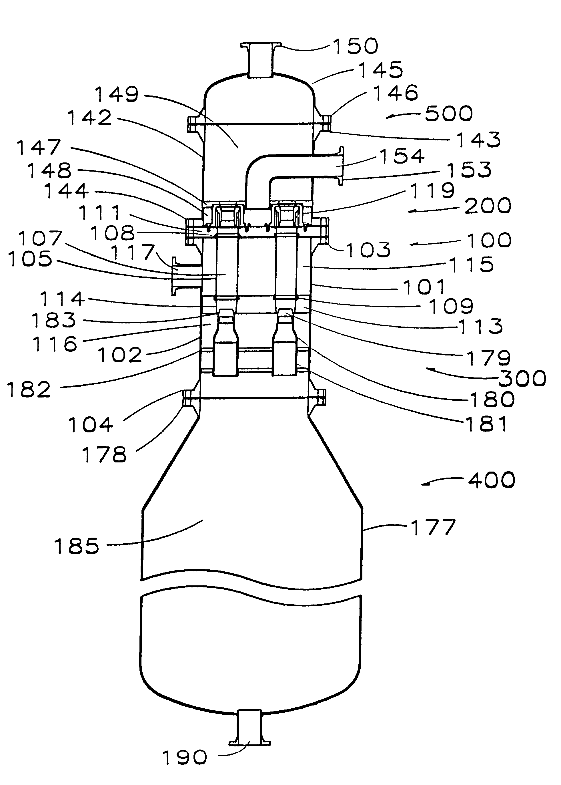
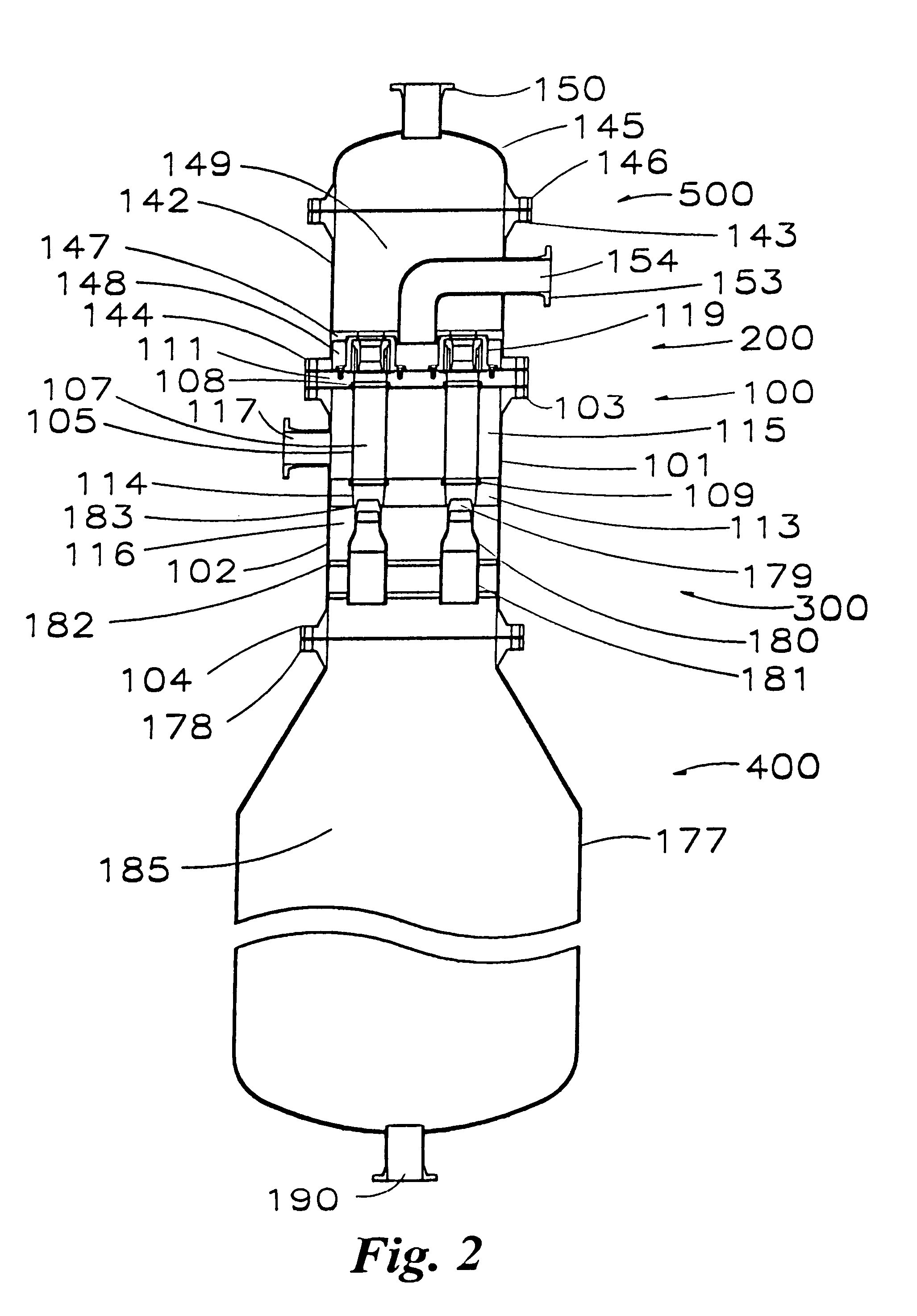
[0064]Referring now to FIGS. 8, 10A, 10B, 11A, 11B, 12A and 12B, the liquid feed and gas exhaust section 200 of the first embodiment is shown in greater detail. A liquid inlet and gas exhaust nozzle assembly 119 is secured over each of the bores 112 in the first tube sheet 111 in axial alignment with the bores and the first or upper end 108 of each tube 105. The liquid inlet and gas exhaust nozzle assembly 119 includes a nozzle housing 120 (FIGS. 10A, 10B) having a generally cylindrical side wall 121 with a radial flange 122 at its bottom end, a larger interior diameter 123 extending upwardly therefrom, a reduced diameter exhaust opening 124 at its top end, and a rectangular liquid inlet nozzle aperture 125 through its side wall tangential to its interior diameter to establish tangential liquid flow of a thin film of incoming liquid. The rectangular nozzle aperture 125 is precisely formed by removing material on the side wall 121 of the nozzle housing to establish liquid communicati...

second embodiment

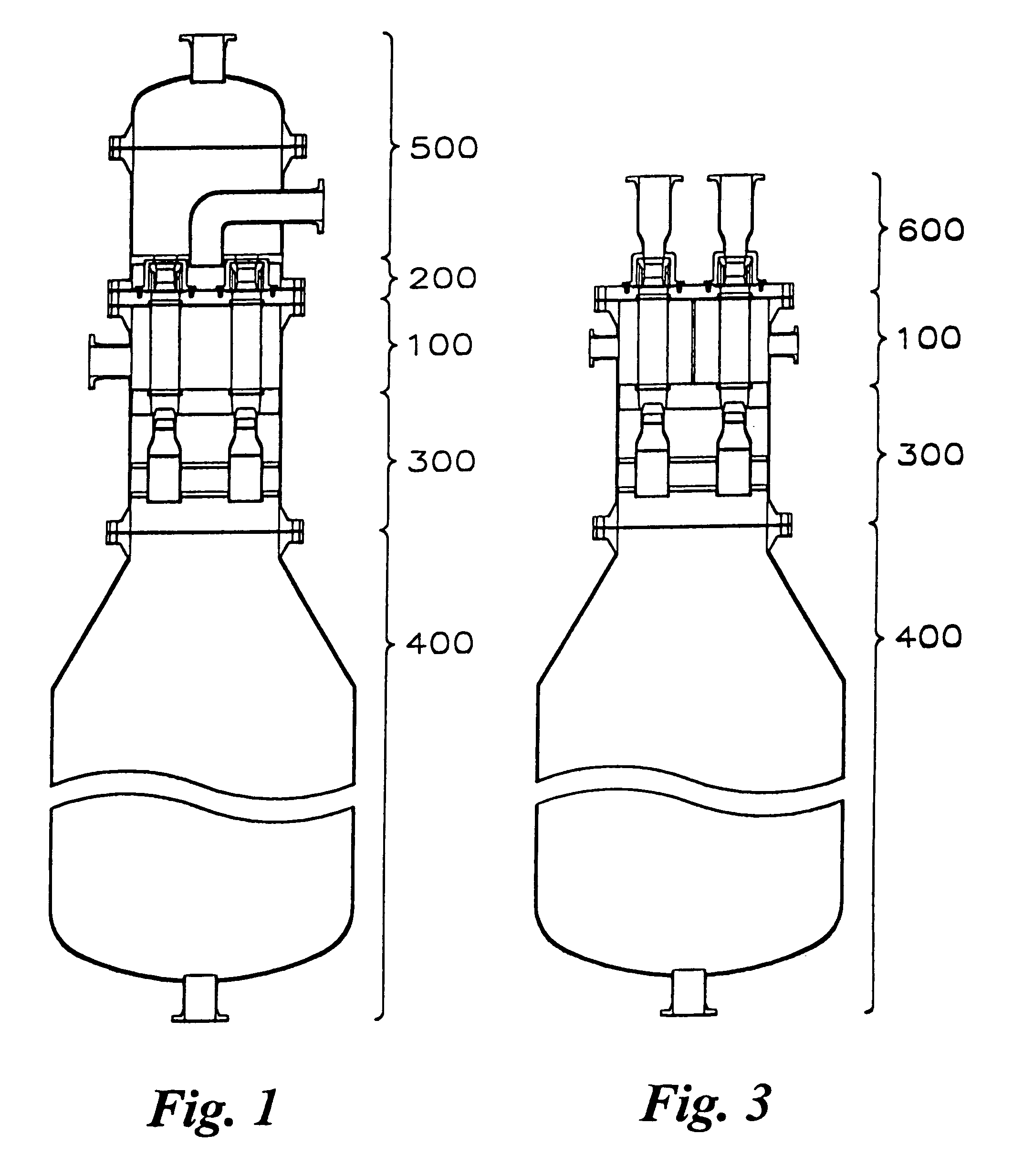
[0072]As shown in FIGS. 13A and 13B, each of the nozzle housings 164 of the second embodiment is a generally cylindrical member having a radial flange 165 at its bottom end with bolt holes in a pattern matching threaded holes in the tube sheet 162, a larger interior diameter 166 extending upwardly therefrom with a reduced diameter exhaust opening 167 at its top end in communication with the interior 169 of an elongate exhaust outlet 168 having a radial flange 170 at its outer end through which gas is exhausted. A liquid inlet 171 extends outwardly from the side of the nozzle housing 164 and, as shown here, has a Victaulic-type coupling groove 172 near its outer end, but not limited thereto. The interior of the liquid inlet 171 has a central bore which receives a pair of replaceable nozzle inserts 173 and 174 held in place by a retainer 175. The insert 173 is cylindrical. As best seen in FIG. 13C, the insert 174 has a curved end 174A matching a curved segment of the interior diameter...


PUM

PropertyMeasurementUnit
Timeaaaaaaaaaa
Pressureaaaaaaaaaa
Flow rateaaaaaaaaaa

Abstract

A method for contacting large volumes of gas and liquid together on a microscopic scale for mass transfer or transport processes wherein the contact between liquid and gas occurs at the interfaces of a multitude of gas bubbles. Multiple porous tubes assembled in a bundle inside a pressure vessel terminate at each end in a tube sheet. A thin film helical liquid flow is introduced into the inside of each porous tube around and along its inside wall. Gas is sparged into the porous media and the liquid film so that an annular two phase flow with a uniform distribution of tiny gas bubbles results. The gas flow is segregated from the liquid flow without first passing through the porous media and through the liquid film. Nozzles at the lower end of the tubes divert liquid flow to a vessel and redirect the gas flow in a countercurrent direction.

Description

CROSS REFERENCE TO RELATED APPLICATION[0001]This application is a divisional of and claims priority of application Ser. No. 10 / 351,629, filed on Jan. 27, 2003, now U.S. Pat. No. 6,830,608, which claims priority of U.S. Provisional Application Ser. No. 60 / 392,498, filed Jun. 28, 2002.BACKGROUND OF THE INVENTION[0002]1. Field of the Invention[0003]This invention relates generally to apparatus and methods for creating and maintaining controlled mass transfer, heat transfer, or chemical reactions, and more particularly to an apparatus and method for contacting industrial volumes of gas and liquid phases in close microscopic scale proximity with each other for the purpose of creating and maintaining controlled mass transfer, heat transfer, or chemical reaction to achieve a particular process.[0004]2. Brief Description of the Prior Art[0005]A wide variety of industrial operations depend on contacting a gas and a liquid together to achieve a process. These operations can generally be categ...

Claims


Application Information

Patent Timeline
IPC IPC(8): B01D53/18B01D19/00B01D3/28B01D3/14
CPCB01D3/28B01D19/0057B01D53/18
Inventor PETERS, JANET K.
Owner JAECO TECH
Why Eureka
Try Eureka