
Ultra portable traffic management system

a traffic management system and portable technology, applied in the direction of traffic signals, roads, instruments, etc., can solve the problems of affecting the safety of people, other accidents may occur at an existing accident or emergency site, emergency site, etc., and achieve the effect of economic production

Inactive Publication Date: 2012-11-27
BONTEMPS EVAN J +1
View PDF11 Cites 62 Cited by
  • Summary
  • Abstract
  • Description
  • Claims
  • Application Information

AI Technical Summary

Benefits of technology

[0012]The needs in the prior art described in the previous paragraphs are met by the present invention. A collapsible, relatively light, ultra portable, traffic management unit is disclosed that may be carried in police cars, emergency vehicles, or other vehicles. At an accident site, site of an emergency, site of road work, work alongside a road side, or wherever else needed for traffic and pedestrian crossing control, one person may take the traffic management unit out of the vehicle in which it is carried, and quickly and easily set it up and program it for use.
[0014]The use of the novel traffic management unit is, for example, advantageous in road work situations where two or more flagmen must be used to alternately control the direction of vehicular traffic through a work area. With the use of one of the novel traffic management units at either end of a road work area and a hand held controller one person can properly control the flow of vehicular traffic through the work area. Similarly, a single police, emergency or other personnel can initially set up or change the visual traffic signals emitted by one or more traffic management units at an accident or emergency site using the hand held controller. Alternatively, the operator of a traffic management unit can program the system to operate automatically and unattended.
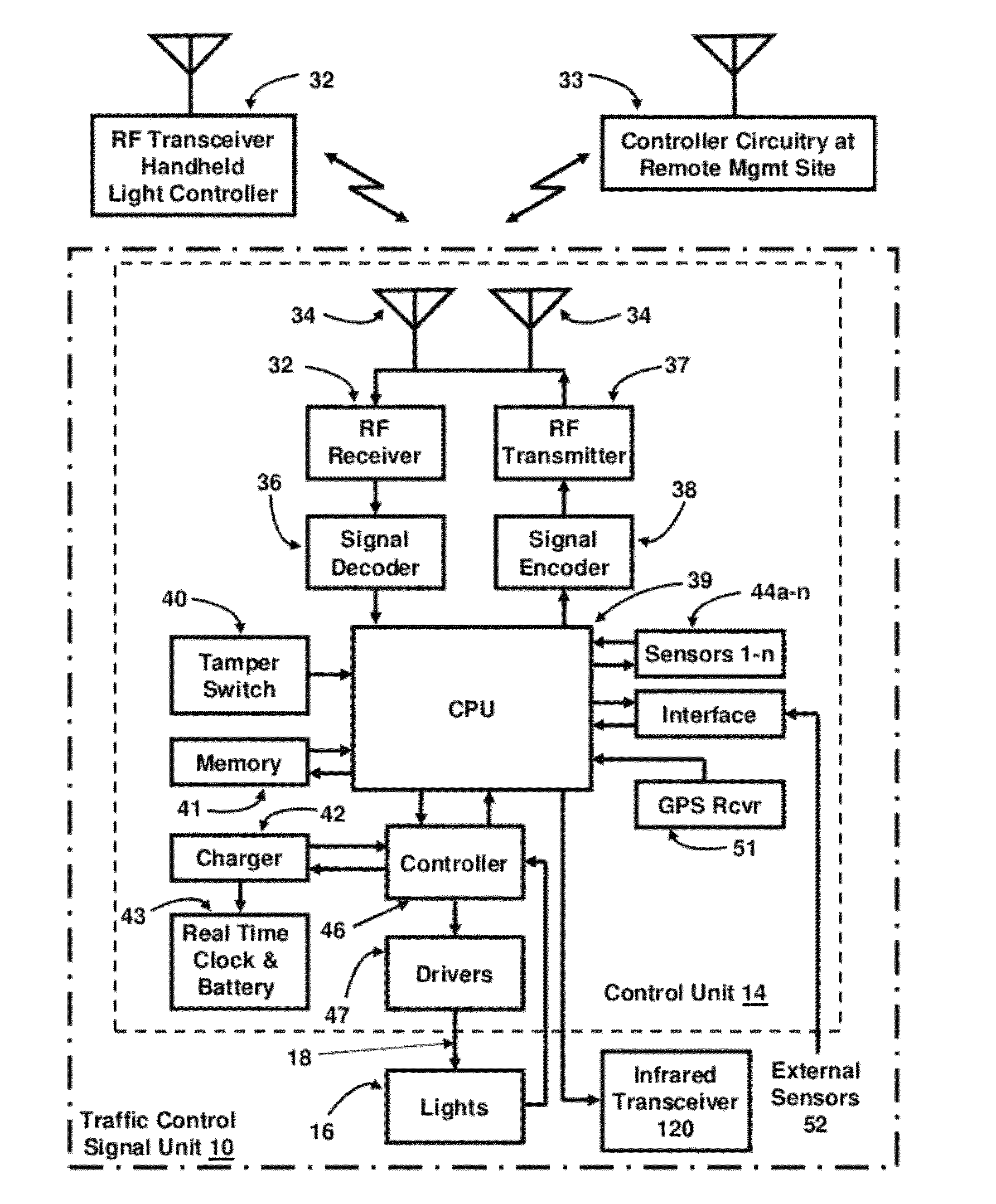
[0017]A tamper switch is included with the control unit, and the switch activates if the traffic management unit is moved even a small amount, which may indicate that the unit is wrongfully being moved in a possible theft attempt. The operation of the tamper switch causes a microprocessor in the control unit to cause an appropriate signal to be transmitted using the RF transmitter. The signal is received at the remote control site, and police or other personnel would be immediately dispatched to the location of the traffic management unit. The tamper switch would also be activated if the traffic management unit is moved inadvertently or by accident which could affect the visual view of the LED light assembly, so the police or other personnel dispatched to the location of the traffic management unit can correct the physical orientation of the unit.
[0021]The pieces of the traffic management unit are modular and may be easily assembled and setup, or disassembled and collapsed to store in a bag that is the size of a large gym bag, or in any other type of container, and the bag or container is easily stored in a small vehicle.

Problems solved by technology

Too often, the extra police officers are not available for assignment to an accident or emergency site and the situation can be dangerous to all people at the site due to lack of traffic control.
Indeed, other accidents may occur at an existing accident or emergency site due to the lack of adequate traffic control.
Using flagmen, law enforcement or emergency personnel to control traffic at vehicular accidents, emergency sites, special events, etcetera is dangerous when it is dark and in inclement weather because it is difficult to see such personnel even when they have flashlights.
However, the trailer carried portable traffic management systems are not very practical at accident or other emergency sites where they are needed almost instantly because of the length of time involved in arranging for the use of one, transporting them the accident site, physically setting them up and programming them.

Method used


Image

  • Ultra portable traffic management system
  • Ultra portable traffic management system
  • Ultra portable traffic management system

Examples


Embodiment Construction

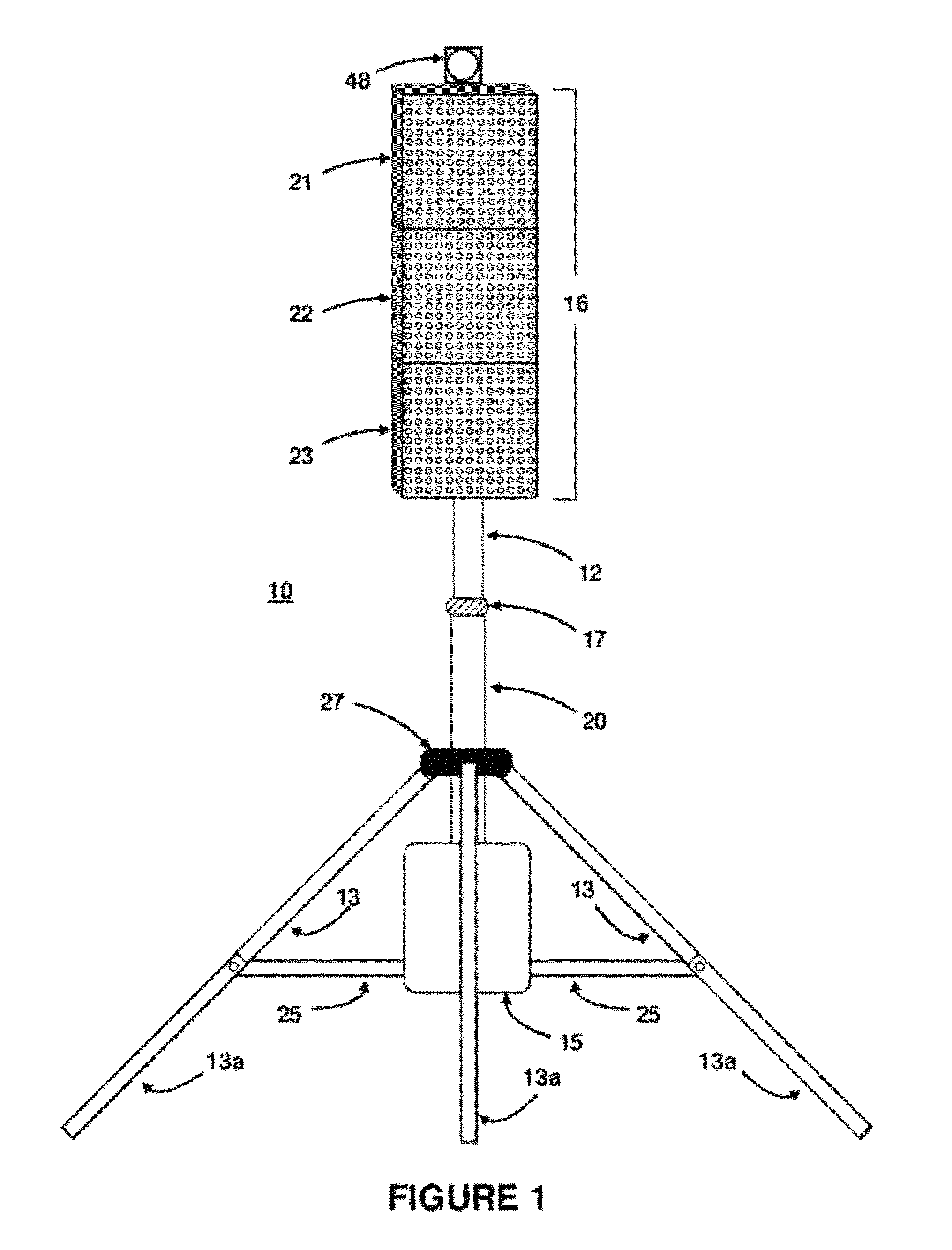
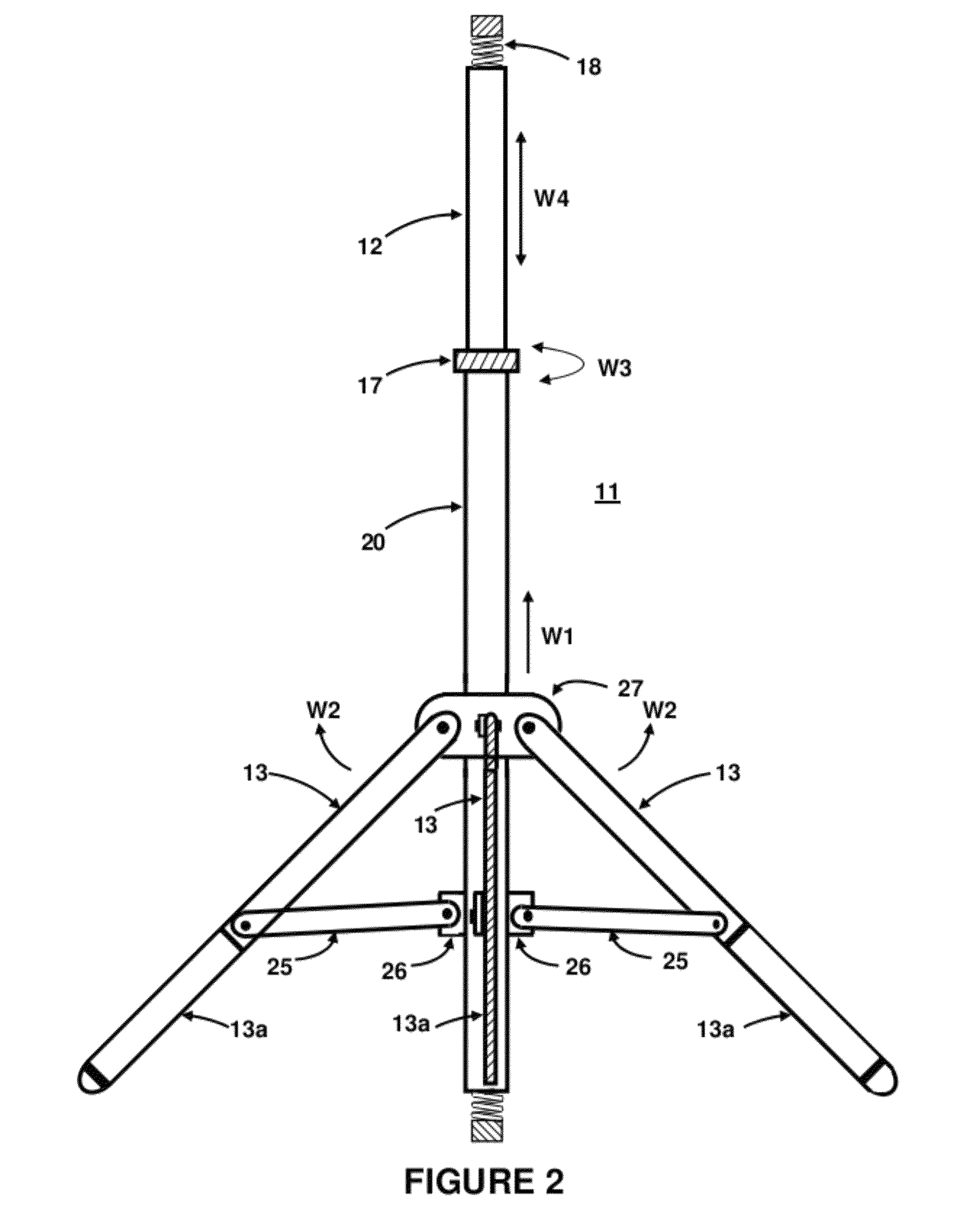
[0037]In FIG. 1 is shown a perspective view of an assembled, portable traffic management unit 10. A unique feature of traffic management unit 10 that facilitates its portability is its ease of assembly and setup, and its ease of disassembly and collapsibility into a relatively small package that can easily be stored in a vehicle. A handheld RF remote control unit 32 for operating the control unit 14 of traffic management unit 10 is not shown in this figure, but is shown in FIG. 10. Briefly, there is an adjustable vertical length stand base 11 that is well known in the art. It has extendable legs 13 and a lower vertical portion 20. The legs 13 each have an extendable portion 13a for positioning unit 10 on non-level and uneven surfaces. Only three legs 13 are shown in FIGS. 1 and 2 for the sole purpose of not cluttering the drawing, but in reality there are usually five legs 13. There is also an extendable upper vertical portion 12 that is extended from within the lower vertical porti...


PUM


Abstract

A portable traffic control unit for temporary use is disclosed that is capable of both automatic and manual operation. The unit is modular and is small enough and light enough that it is easily carried in a police, emergency or other vehicle and can be set up and programmed for use by one person. The unit has a bright LED display typically having red, orange, green lights, and flashing white strobe LEDs that are microprocessor controlled. The unit has a radio receiver that receives RF signals used to control the operation of the unit, and the signals are received from a handheld RF transmitter used at the site of the unit, or are received from an RF transmitter at a remote control site. Various sensors may be attached to the unit to provide information that is transmitted to the handheld remote control and / or to the remote control site using an RF transmitter that is part of the unit. Multiple traffic control units operating at a common site can communicate with each other to facilitate operations.

Description

RELATED APPLICATION[0001]This utility patent application claims benefit under U.S. Provisional Patent Application No. 61 / 218,967, entitled “Ultra Portable Traffic Management System”, filed on Jun. 21, 2009.FIELD OF THE INVENTION[0002]This invention relates to portable, temporary traffic management systems that may be used in emergency, road work and other situations and which can be easily set up and operated by one person, or operate in unattended automatic modes when needed.BACKGROUND OF THE INVENTION[0003]Traditional traffic control for highway road works and the like is accomplished by one or more policemen or traffic control persons known as “flagmen”, that are individuals with handheld signs or flags redirecting traffic or signaling the traffic to slow down or stop for road works or other activity ahead. In addition, at vehicular accident sites one or more policemen often must manage traffic flow while another policeman must gather information, take pictures, call for fire tru...

Claims


Application Information

Patent Timeline
IPC IPC(8): G08G1/095
CPCG08G1/07G08G1/0955
Inventor BONTEMPS, EVAN J.TERRIEN, JR., THOMAS F.
Owner BONTEMPS EVAN J
Learn More