
Burner for combustion of fuel in pellet or granular form

Inactive Publication Date: 2012-12-04
SWANSON HAROLD ANGUS
View PDF10 Cites 15 Cited by
  • Summary
  • Abstract
  • Description
  • Claims
  • Application Information

AI Technical Summary

Benefits of technology

"The present invention is a pellet burner that can burn fuel containing up to 7% ash without clogging the grate. The burner has a combustion chamber with a rotating grate that moves ash particles through outlet apertures. The grate has recesses that allow ash particles to be broken into smaller fragments by the rotating member. The burner also has a cylindrical wall and a spring-biased door for expelling large ash particles. The motor for rotating the grate is powered by a horizontal-axis motor via a bevel gear. The technical effects of this invention are improved combustion efficiency, reduced emissions, and reduced maintenance costs."

Problems solved by technology

For example, grass or hay pellets usually have over 5% ash content, and may be contaminated with sand and potassium chloride which produce glassy materials, in the form of clinkers or slag, when it burns.
Such combustion products, which are usually heavier than the light hay or grass pellets, build up on a conventional burner grate and may put out the fire after a few hours.

Method used


Image

  • Burner for combustion of fuel in pellet or granular form
  • Burner for combustion of fuel in pellet or granular form
  • Burner for combustion of fuel in pellet or granular form

Examples


Embodiment Construction

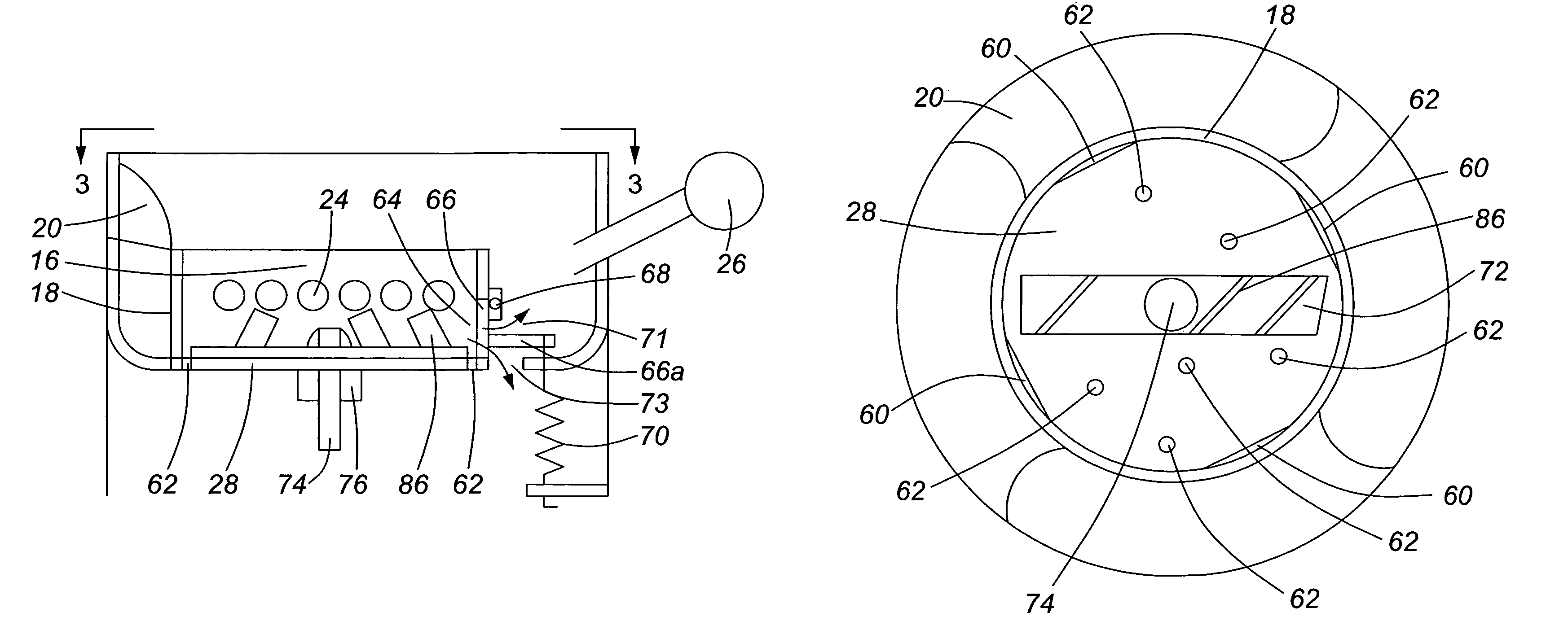
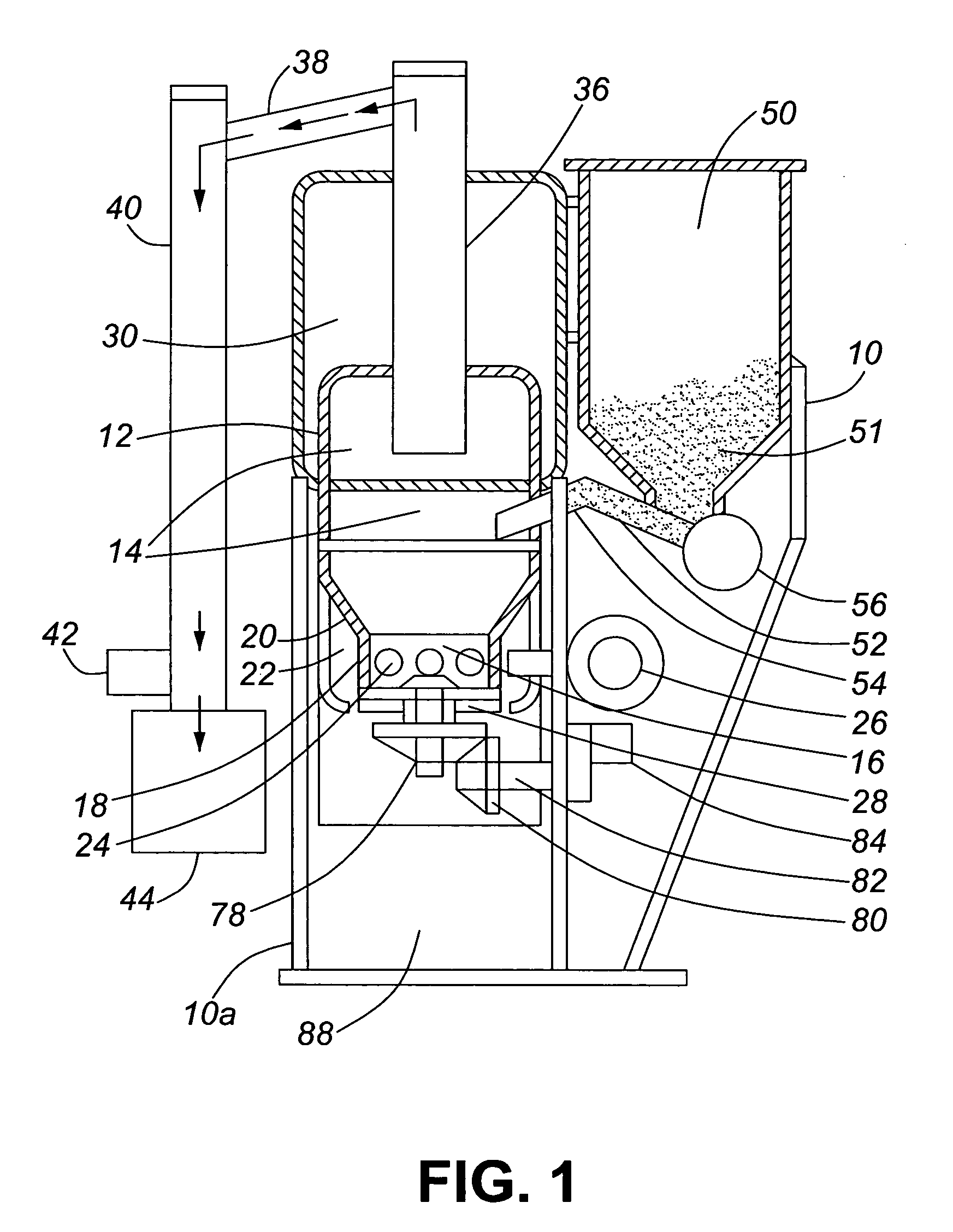
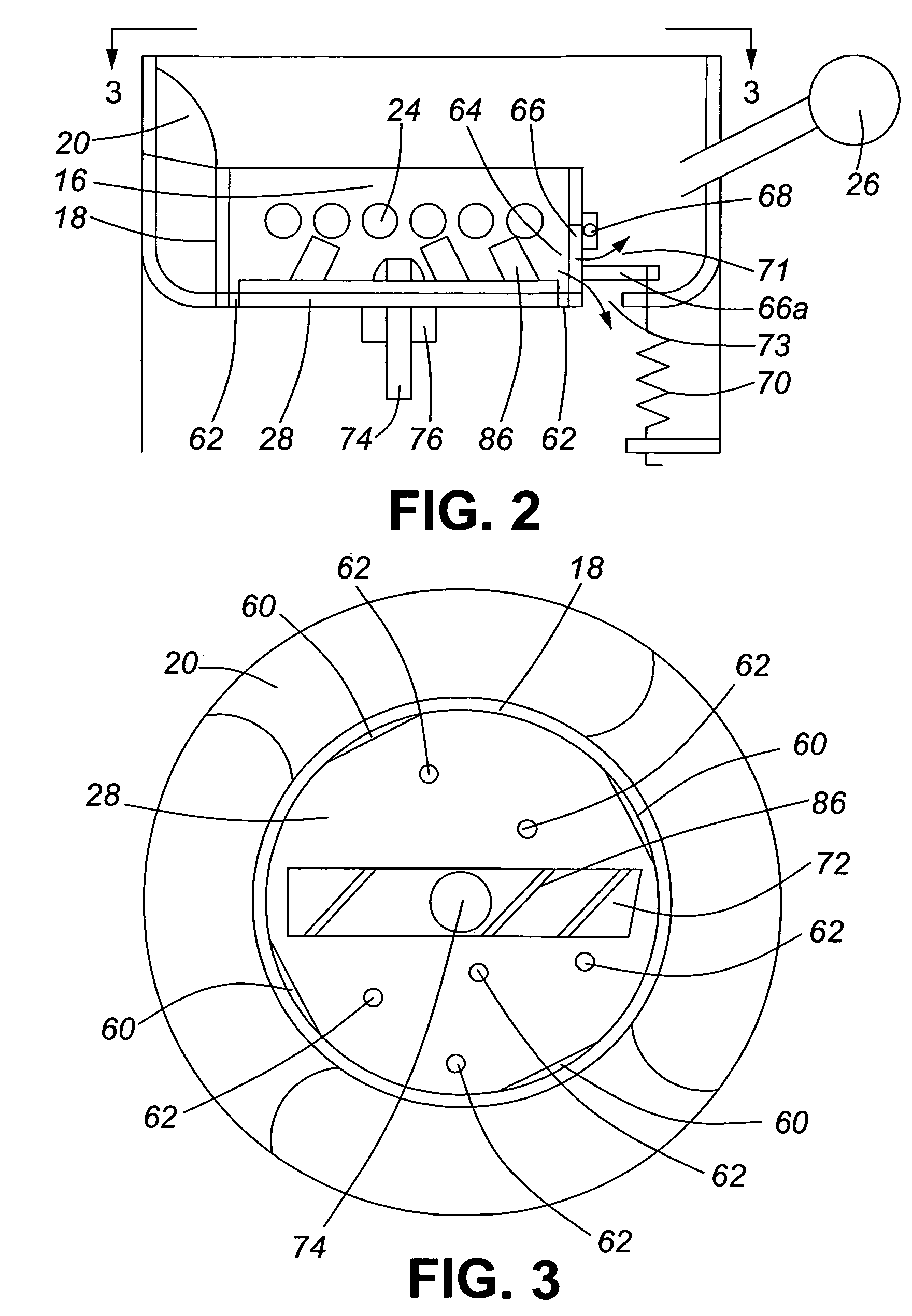
[0022]Referring to FIGS. 1 to 3, the pellet burner, which is in the form of a water heater, has a support frame 10, including a central part with legs 10a which support a casing 12 surrounding a combustion chamber 14. The lower part of chamber 14 is in the form of a burn pot 16 having a cylindrical wall 18 of reduced diameter compared to the upper part of chamber 14. Wall 18 is connected to the upper part of the combustion chamber 14 by an upwardly diverging wall portion 20 which forms the top of an annular inlet air chamber 22, which chamber communicates with the burn pot 16 via air inlet ports 24 spaced around the wall 18. Annular chamber 22 receives forced air for combustion from an air blower 26. The bottom of the burn pot 16 is formed by a grate 28, having a special ash removal mechanism described below.

[0023]This embodiment of burner being in the form of a water heater, an upper portion of the combustion chamber 14 is surrounded by a lower part of a water chamber 30. A chimney...


PUM


Abstract

A burner for fuel in pellet or granular form in which the fuel has a high ash content, for example grass or hay pellets in which the ash content is 5% or more. The burner has a combustion chamber with a grate at its lower end, into which fuel and air are fed, the combustion chamber having a hot gas outlet for exhausting combustion gases. The grate is provided with a rotary member having upstanding vanes which is adapted to continually move ash or clinker on the grate through outlet apertures spaced around the grate. The grate is a generally planar, horizontal surface which is imperforate apart from the outlet apertures; air inlet ports are arranged in a circumferential wall surrounding the grate.

Description

BACKGROUND OF THE INVENTION[0001]1. Field of the Invention[0002]The present invention relates to a burner for combustion of fuel in pellet or granular form, and may be referred to as a “pellet burner” or “pellet furnace”. The invention is especially designed to operate with pellet or granular fuel of high ash content, for example grass or hay pellets. While the invention is particularly described in relation to a water heater or boiler, the invention may equally be applied to other combustion devices, e.g. a stove or space heater.[0003]2. Prior Art[0004]Pellet burners are known both for space heating and water heating. Usually, the pellets used are formed from wood, e.g. sawdust, and have an ash content usually less than 1%. When such pellets are burnt the ash is very light, and the combustion air fed to the burner, which is usually forced air provided by a fan, blows the ashes out of the top of the combustion chamber through a chimney.[0005]It would be desirable to use pellets from...

Claims


Application Information

Patent Timeline
Patent Type & Authority Patents(United States)
IPC IPC(8): F23H13/00
CPCF23B50/12F23H13/02F23H15/00F24H1/187F24H6/00F23B30/00F24D2200/067
Inventor SWANSON, HAROLD ANGUS
Owner SWANSON HAROLD ANGUS
Learn More