Method and arrangement for controlling flush water volume

a technology of flushing water and flow, applied in the direction of valve operating means/release devices, couplings, mechanical equipment, etc., can solve the problems of obvious undesirable, inability to control the flow volume of water, and widespread waste of water by users, so as to achieve effective control of the flow volume of flushing water

Active Publication Date: 2012-12-04
ADVANCED MODERN TECH
View PDF5 Cites 13 Cited by
  • Summary
  • Abstract
  • Description
  • Claims
  • Application Information

AI Technical Summary

Benefits of technology

[0010]A main object of the present invention is to provide a flush system comprising a flush water control arrangement which is capable of effectively controlling a flow volume of flush water during a flushing operation.
[0011]Another object of the present invention is to provide a flush system comprising a water control arrangement, wherein a flushing shaft extended from a valve seat of the flush system is pushed at two spacedly apart positions on the flushing shaft so as to effectively control the period for which the valve seat is opened for effectively controlling the volume of flush water at two separate modes of operation.
[0012]Another object of the present invention is to provide a flush system comprising a water control arrangement, which does not in any way interfere with a normal operation of the flush system (except an adjustment of the volume of flush water), so as to allow the water control arrangement to be incorporated into a wide range of conventional flush systems without undue burden on the part of flush system manufacturers. In other words, the present invention can be kept to have the minimal manufacturing cost.

Problems solved by technology

A major drawback for this conventional toilet flush system is that the user is unable to control the volume of water flow so that unnecessary waste of water is prevalent.
This is obviously undesirable from environmental as well as economical point of view.
However, the major problem for these kinds of water adjustment mechanisms is that their efficacy of effectively controlling the volume of flushing water among a plurality of operation modes is in doubt.
However, the reality is that very often, there is no noticeable or significant difference in water consumption between these two modes of operations so that there is no practical distinction between these two modes of operations.
From engineering point of view, when the water adjustment mechanism produces no significant difference in water consumption, there is actually no reason or incentive to produce a flush system having such a water adjustment mechanism because it will certainly increase the manufacturing cost of that flush system.
It is submitted that the main reason for this ineffectiveness in controlling the volume of flush water is that one is hard to accurately control the period for which the relief valve is opened by one single actuating member.

Method used


Image

  • Method and arrangement for controlling flush water volume
  • Method and arrangement for controlling flush water volume
  • Method and arrangement for controlling flush water volume

Examples


Embodiment Construction

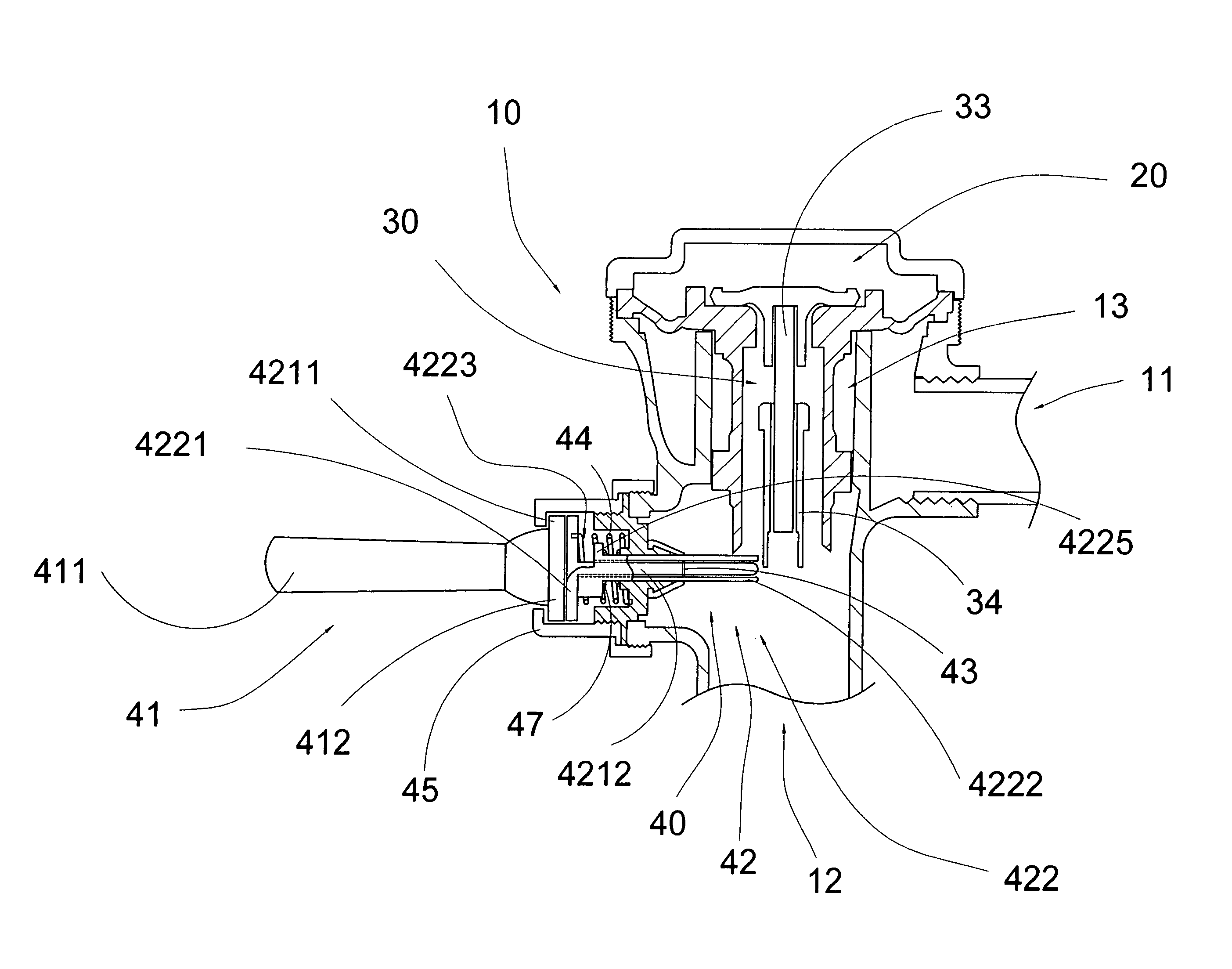
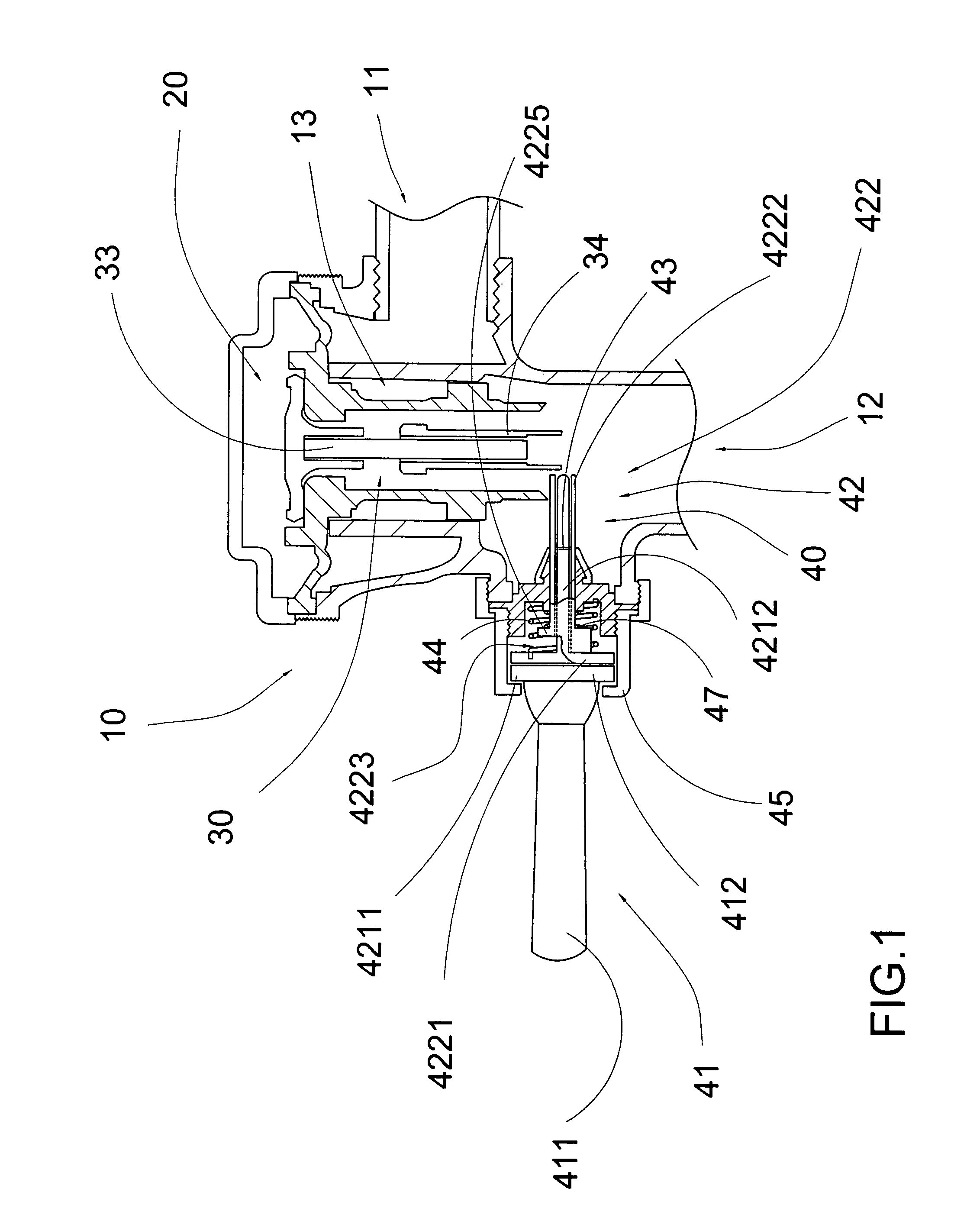
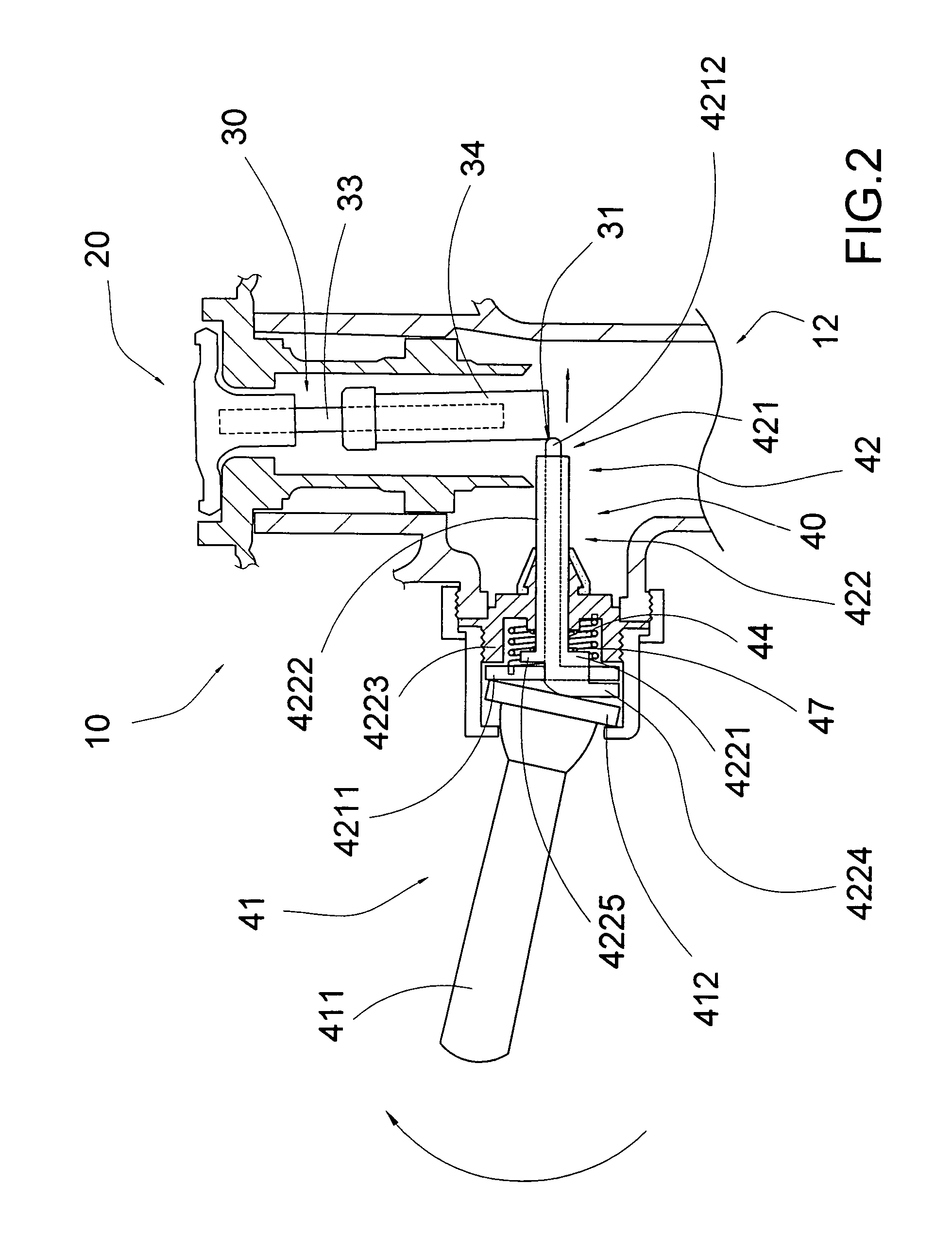
[0042]Referring to FIG. 1 to FIG. 6 of the drawings, a flush system according to a preferred embodiment of the present invention is illustrated, in which the flush system for a toilet comprises a valve body 10, a valve seat 20, a flushing shaft 30, and a water control arrangement 40.

[0043]The valve body 10 has a water inlet 11 communicating with a water source, a water outlet 12, and a water chamber 13 communicating between the water inlet 11 and the water outlet 12.

[0044]The valve seat 20 is supported in the valve body 10 to move between a normal idle position and a flushing position, wherein at the idle position, the valve seat 20 is sealed at the water chamber 13 for retaining a water pressure within the water chamber 13 so as to block flush water flowing from the water inlet 11 to the water outlet 12, wherein and at the flushing position, the valve seat 20 is moved to relief the water pressure for allowing the flush water flowing towards the toilet through the water outlet 12 so...


PUM


Abstract

A flush system includes a valve body, a valve seat, a flushing shaft and a flush water control arrangement which includes a flush actuator and a water control pusher. The flush actuator is adapted to move between a high and a low volume actuating position. The water control pusher includes a low and a high volume pusher member spacedly extended from the flush actuator, in such a manner that when the flush actuator is moved to the high volume actuating position, the high volume pusher member is driven to move to pivotally move the flushing shaft at the higher pushing position for producing a high volume of flush water, wherein when the flush actuator is move to the low volume actuating position, the low volume pusher member is driven to move to pivotally move the flushing shaft at the lower pushing position for producing a low volume of flush water.

Description

CROSS REFERENCE OF RELATED APPLICATION[0001]This is a non-provisional application of a provisional application having an application No. 61 / 004,681 and a filing date of Nov. 28, 2007.BACKGROUND OF THE PRESENT INVENTION[0002]1. Field of Invention[0003]The present invention relates to a flush system, and more particularly to a flush system comprising a flush water control arrangement which is capable of effectively controlling a flow volume of flush water during a flushing operation.[0004]2. Description of Related Arts[0005]Urinal and toilet flush systems have been well-known as one of the most significant inventions in the last century. A conventional toilet or urinal flush system comprises a valve body having a water inlet and a water outlet, a diaphragm having a water channel communicating between the water inlet and the water outlet, a relief valve disposed at the diaphragm for blocking the water flowing from the water inlet to the water outlet through the water channel, and a flu...

Claims


Application Information

Patent Timeline
Patent Type & Authority Patents(United States)
IPC IPC(8): F16L37/28
CPCE03D3/02E03D5/092
Inventor MAERCOVICH, JORGE
Owner ADVANCED MODERN TECH
Why Eureka
Try Eureka