Device for adjusting camber and/or toe

a camber and/or toe technology, applied in the direction of resilient suspensions, vehicle springs, vehicle components, etc., can solve the problems of inability to implement required multiplication through a simple pinion/gear stage, spatial conditions that do not allow random placement of drives

Active Publication Date: 2012-12-04
AUDI AG
View PDF8 Cites 22 Cited by
  • Summary
  • Abstract
  • Description
  • Claims
  • Application Information

AI Technical Summary

Benefits of technology

[0007]The object is solved in accordance with the invention by a device for adjusting camber and / or toe of the wheels of wheel suspensions, in particular for motor vehicles, comprising a wheel carrier on which the respective wheel is rotatably supported and which is subdivided in a carrier part holding the wheel, a guide part connected with the wheel suspension, and two rotary parts, in particular control cylinders, which are arranged in-between and rotatable relative to one another as well as to the carrier part and to the guide part about a common rotation axis and which can be respectively adjusted in both rotation directions by a drive and a servo drive, wherein the servo drive for at least one of the rotary parts or control cylinders, preferably for both rotary parts, is configured as planetary gear train, and the planetary gear train is arranged about the rotary part in particular radially externally. As a consequence of increased tooth meshing, such a gear mechanism provides a robust torque transmission and torque support and can advantageously be constructively integrated in the wheel carrier.
[0009]Preferably, the electric motor-driven annulus of the planetary gear train can be rotatably supported on the carrier part and / or on the guide part, with the inner planetary gears being supported on bearing pins of the carrier part and / or guide part and meshing with the annulus and a sun gear arranged on the control cylinder. As the annulus has a relatively large diameter, driving torque can be reliably introduced via the annulus while being able to select beneficial transmission ratios. Moreover, the control cylinders can easily be manufactured and provide easy clearance for a cardan joint extending centrally through the control cylinders. Using an annulus, large planet gears (four planet gears) and a large gear on the adjustment cylinder establishes a far greater contact ratio than a single tooth engagement with small pinion (only one pinion).
[0010]The annulus of the planetary gear train is floatingly supported preferably via a double-row rolling-contact bearing on the carrier part and / or guide part, resulting in a particularly weight-beneficial construction.
[0011]Furthermore, the annulus may be driven directly by an electric disk motor having a disk rotor mounted on the outer circumference of the annulus and stator windings mounted on the carrier part and / or guide part. Having minimum, weight-favorable stator windings enables the disk motor to introduce high drive torques in both rotational directions and easy ring-shaped arrangement on the carrier part and / or guide part of the wheel carrier and optionally within the wheel rim.
[0012]When a wheel suspension is involved which is known per se and has two axis-parallel projecting and diametrically confronting cantilevers or universal-joint fork on each of the carrier part and the guide part for support of a universally mounted support ring, the planet gears are arranged according to an advantageous refinement of the invention in a particularly constructively and spatially space-saving manner in the respective clearances between the cantilevers. In particular, in order to increase tooth engagement, respectively four planet gears are distributed symmetrically about the circumference between the cantilevers. The four pockets or clearances of the universal-joint fork are available for installation of the planet gears. As a result, the drive can be made very compact.
[0014]Finally, a covering cap may be provided between the disk motor and the corresponding control cylinders for encapsulating the planetary gear train and to protect the planetary gear train against harmful environmental impacts like splash water, dirt, etc. The covering cap may be mounted to the ring-shaped housing of the disk motor and seal each of the corresponding control cylinders through interposition of a ring seal.

Problems solved by technology

On the one hand, the strength of the gearing has proven problematic in the context of dimensioning the required motor power and calculating the gear stage.
On the other hand, the required multiplication cannot be implemented through a simple pinion / gear stage.
Furthermore, spatial conditions do not allow to randomly place the drive in axial measuring chain or in radial measuring chain.

Method used


Image

  • Device for adjusting camber and/or toe
  • Device for adjusting camber and/or toe
  • Device for adjusting camber and/or toe

Examples


Embodiment Construction

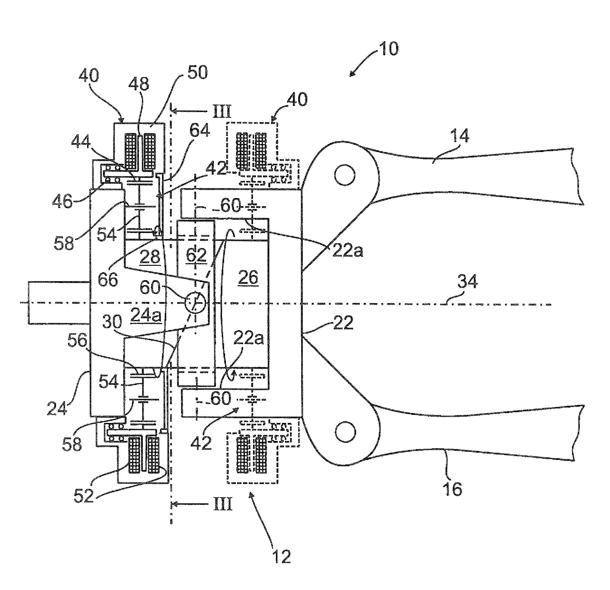
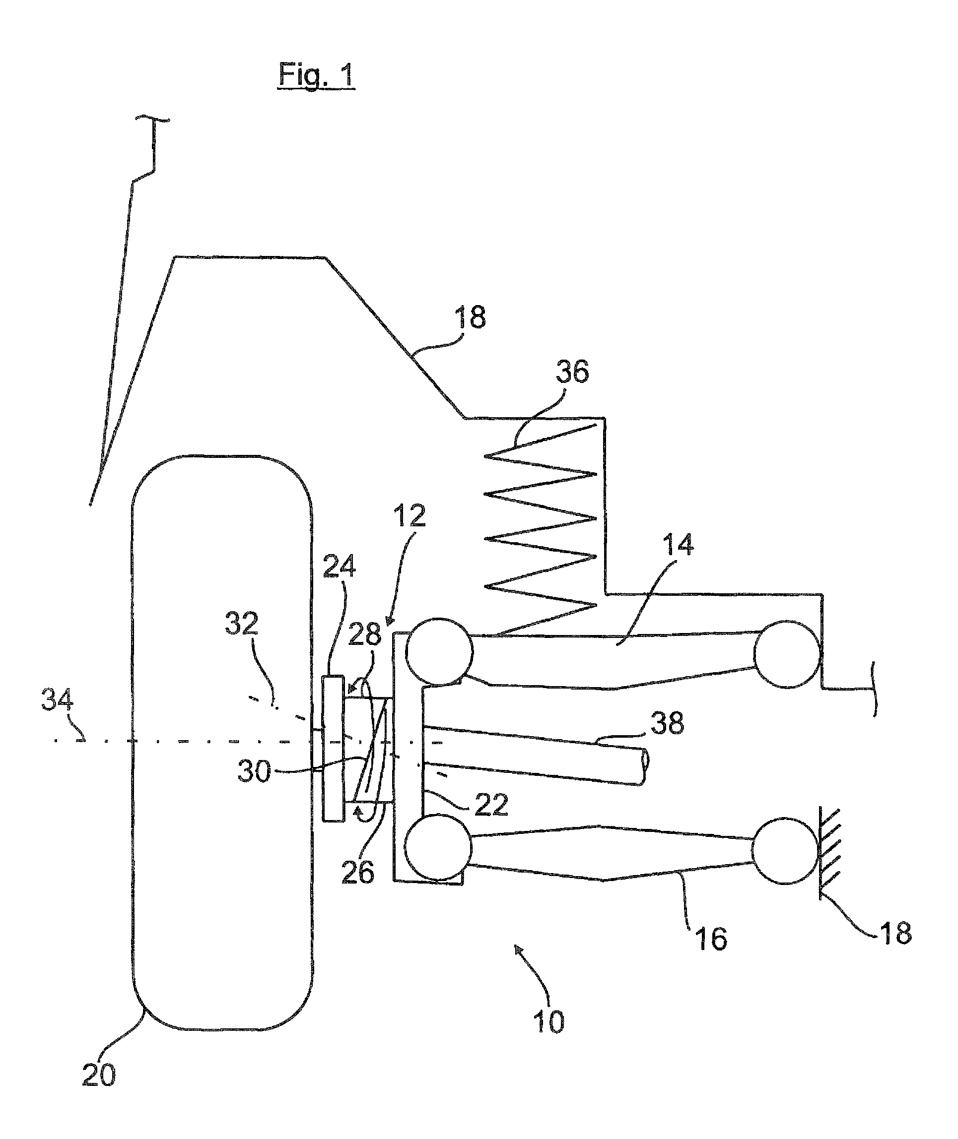
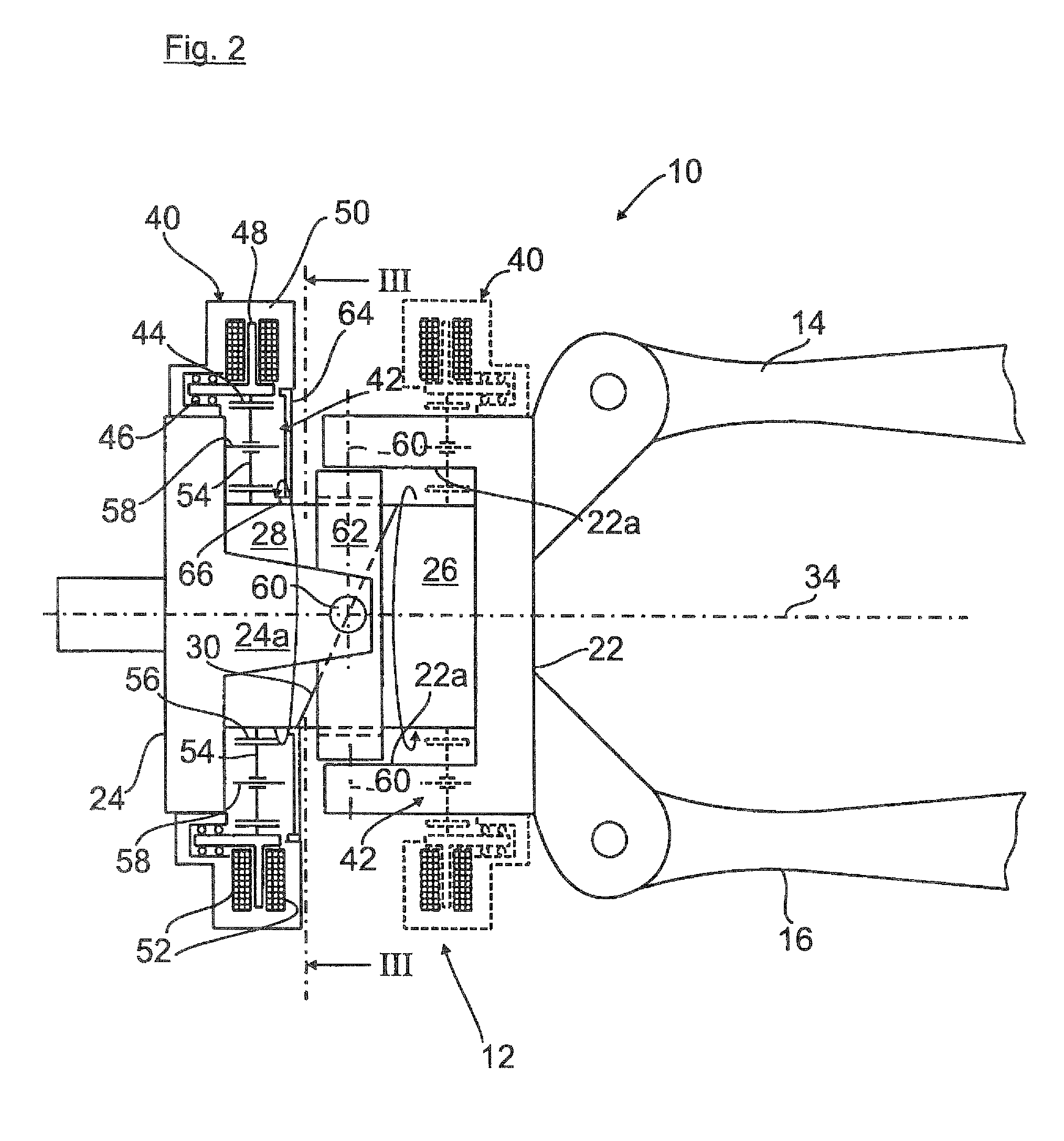
[0019]FIG. 1 shows a rough schematic illustration of a wheel suspension 10 for motor vehicles which has a wheel carrier 12 articulated via transverse links 14, 16 as wheel guide elements to a body 18, hinted here only.

[0020]The wheel carrier 12 which rotatably holds the wheel 20 is subdivided in a guide part 22 which is articulated to the transverse links 14, 16, a carrier part 23 which holds the wheel 20 via a respective wheel bearing (not shown), and two control cylinders 26, 28 which are rotatably supported on the guide part 22 and the carrier part 24 and adjustable about a rotation axis 32 extending in perpendicular relationship to confronting inclined surfaces 30. By pivoting one or both control cylinders 26, 28, the carrier part 24 is tilted in relation to the wheel rotation axis 34 to thereby implement an adjustment of the toe and / or camber of the wheel 20 of the wheel suspension 10.

[0021]The wheel load is supported in a known manner by a support spring 36 in relation to the ...


PUM


Abstract

The invention relates to a device for adjusting the camber and / or toe of the wheels (20) of wheel suspensions (10), especially for motor vehicles, including a wheel carrier (12) on which the respective wheel (20) is rotatably mounted and which is subdivided into a carrier part (24) receiving the wheel, a guide part (22) connected to the wheel suspension (10), and two rotary parts, especially control cylinders (26, 28), arranged between the carrier part and the guide part and rotatable in relation to each other, to the carrier part (24) and to the guide part (22) about a common rotation axis (32). Each of the rotary parts can be moved by a drive (40) and a servo drive (42) in both directions of rotation. According to the invention, the servo drive (42) is designed for at least one of the rotary parts (26, 28) as a planetary gear train (42), and the planetary gear train (42) is especially radially externally arranged around the rotary part (26, 28).

Description

CROSS-REFERENCES TO RELATED APPLICATIONS[0001]This application is the U.S. National Stage of International Application No. PCT / EP2010 / 002678, filed May 3, 2010, which designated the United States and has been published as International Publication No. WO 2010 / 130342 and which claims the priority of German Patent Application, Serial No. 10 2009 021 477.1, filed May 15, 2009, pursuant to 35 U.S.C. 119(a)-(d).BACKGROUND OF THE INVENTION[0002]The invention relates to a device for adjusting camber and / or toe of the wheels of wheel suspensions, in particular for motor vehicles.[0003]Various technical solutions with respect to rear-axle steering of a (road) vehicle are available. In general, the tie rod is pushed or also its length is modified. Moreover, there exist configurations with split wheel carrier, as described in US 20020036385 or in FR 2884795 for example. The rotary parts or control cylinders determinative for the camber and / or toe of the wheel are adjusted hereby by servo drive...

Claims


Application Information

Patent Timeline
Patent Type & Authority Patents(United States)
IPC IPC(8): B60G3/26
CPCB60G7/006B60G7/008B62D17/00B60G2200/144B60G2200/46B60G2200/462B60G2202/42B60G2204/419B60G2204/42B60G2206/50
Inventor MICHEL, WILFRIEDMULLER, HUGOMEITINGER, KARL-HEINZKOSSIRA, CHRISTOPHSCHMID, WOLFGANG
Owner AUDI AG
Why Eureka
Try Eureka