Flexible illumination device for simulating neon lighting

a technology of illumination device and neon lighting, which is applied in the direction of lighting support device, instruments, lighting and heating apparatus, etc., can solve the problems of limited flexibility of known compounds used to produce leaky waveguides, and compounds with enhanced flexibility generally do not have the requisite light scattering properties, etc., to achieve enhanced flexibility and simulate

Active Publication Date: 2012-12-04
LUMINII PURCHASER LLC
View PDF106 Cites 19 Cited by
  • Summary
  • Abstract
  • Description
  • Claims
  • Application Information

AI Technical Summary

Benefits of technology

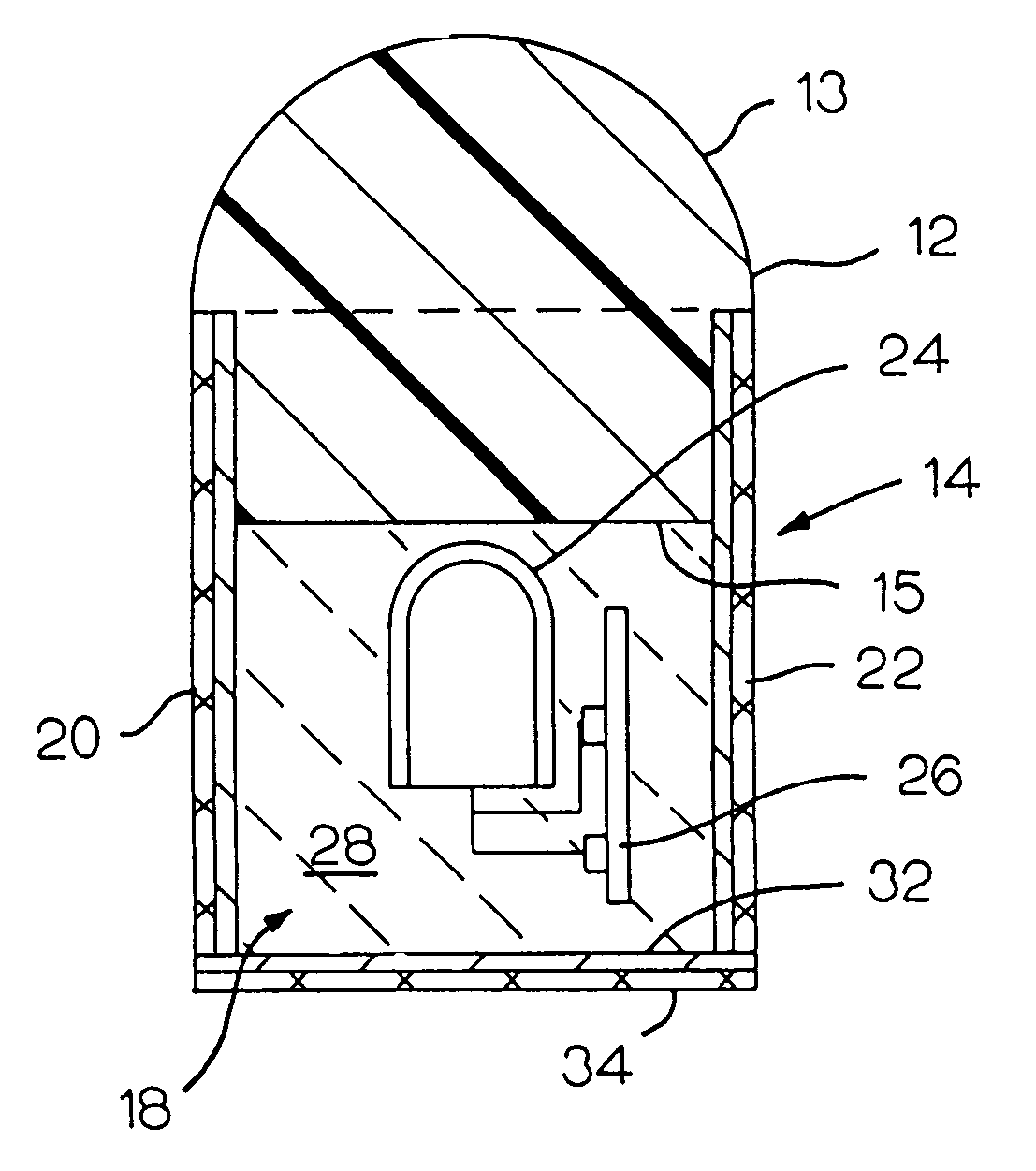
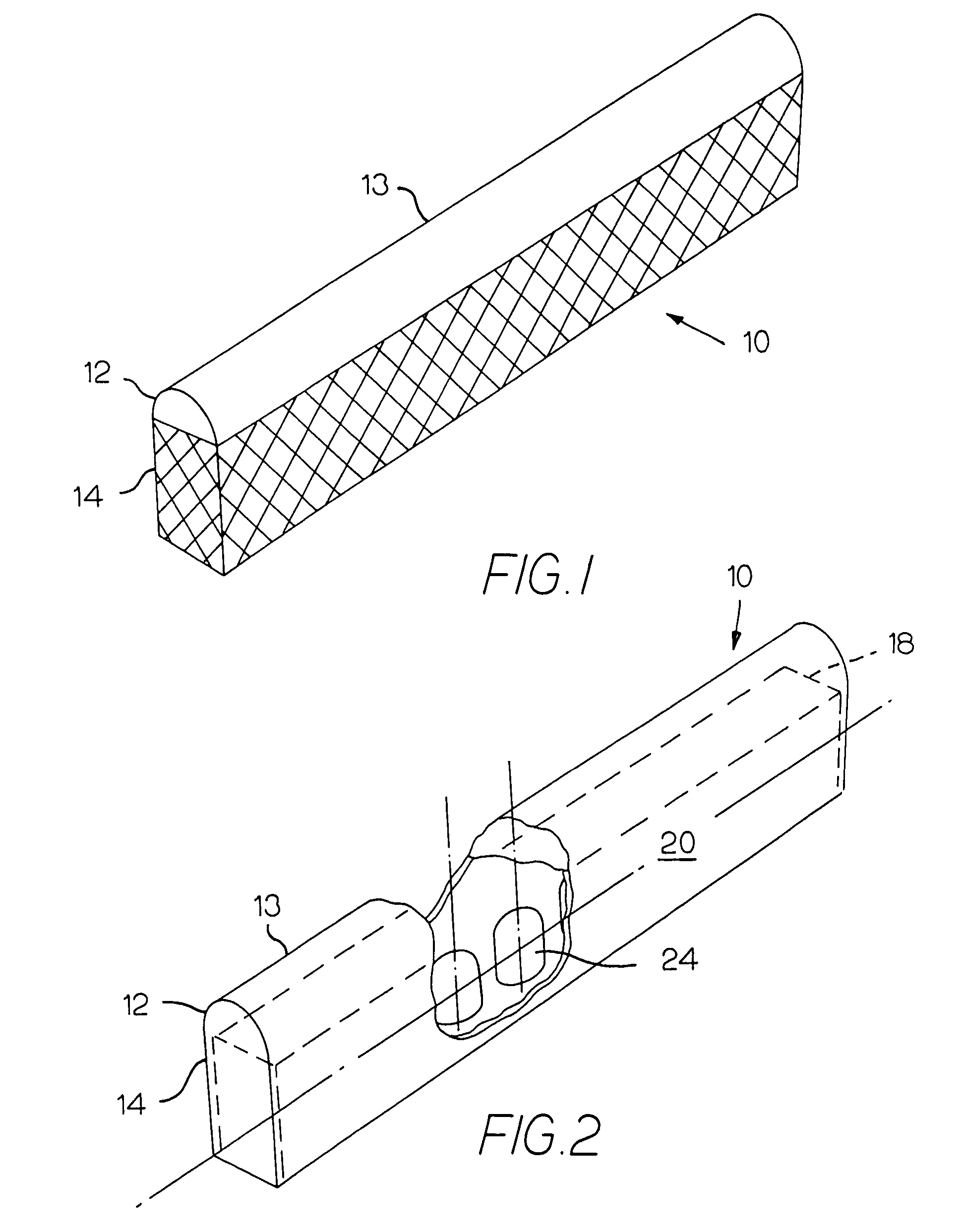
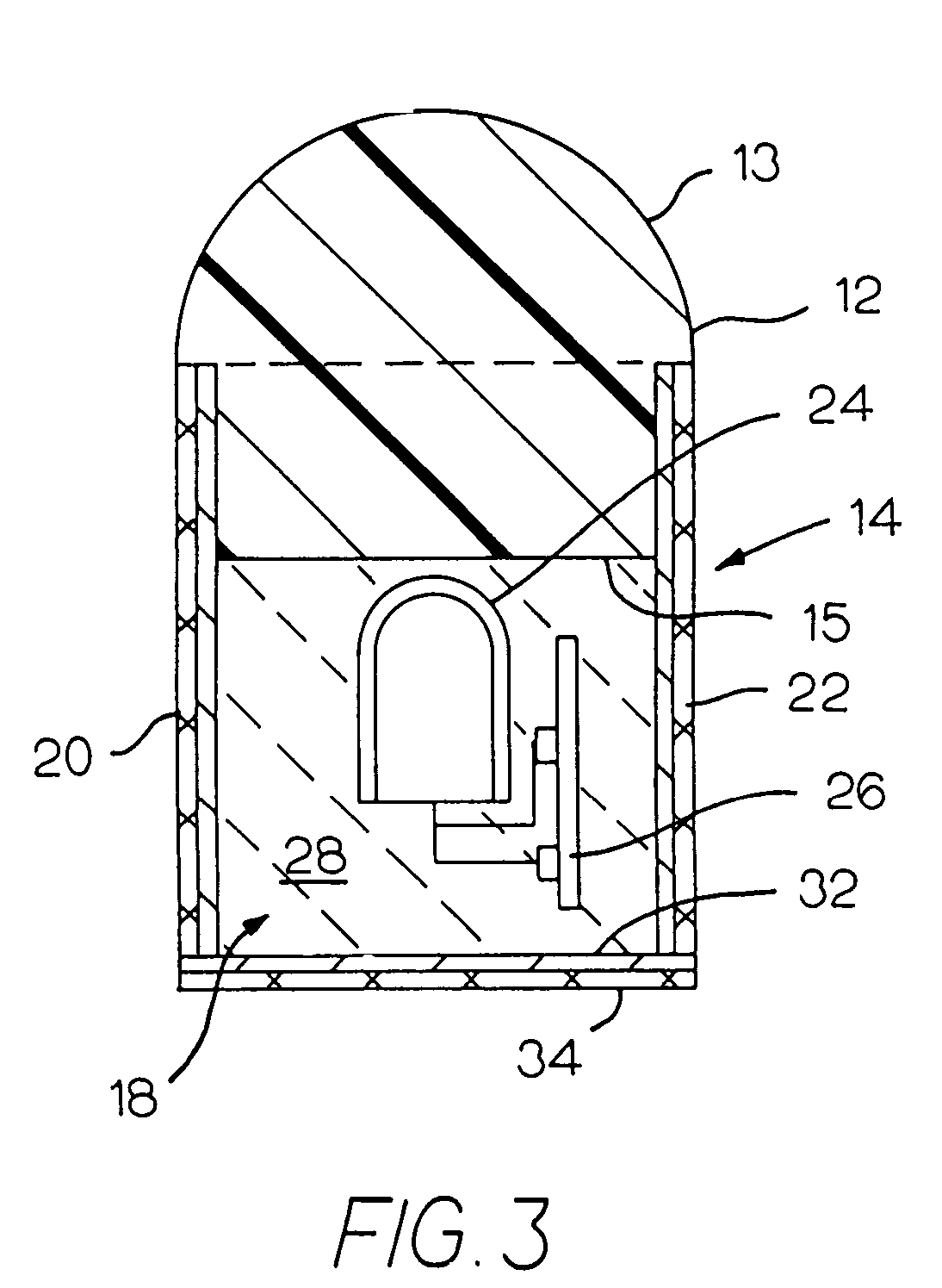
[0011]The present invention is an illumination device that is an effective simulator of neon lighting in that it provides for an essentially uniform light intensity distribution pattern over its entire lateral light-emitting surface, but equally important, the illumination device has enhanced flexibility. To accomplish this, the preferred illumination device uses a high-intensity, but dimensionally small, light source (e.g., high-intensity, light-emitting diodes) together with an element that acts both as an optical waveguide and light scattering member, thus permitting light to exit laterally out of its surface, a so-called “leaky waveguide.” By placing the light source contiguous such a leaky waveguide in a specific manner so as to cause the waveguide to uniformly glow over its light-emitting surface, applicants are able to obtain an illumination device that rivals or surpasses the uniform glow of neon tubing.

Problems solved by technology

As mentioned above, known compounds used to produce leaky waveguides have limited flexibility, while compounds with enhanced flexibility generally do not have the requisite light scattering properties.

Method used


Image

  • Flexible illumination device for simulating neon lighting
  • Flexible illumination device for simulating neon lighting
  • Flexible illumination device for simulating neon lighting

Examples


Embodiment Construction

[0022]The present invention is an illumination device that is an effective simulator of neon lighting in that it provides for an essentially uniform light intensity distribution pattern over its entire lateral surface, but equally important, the illumination device has enhanced flexibility.

[0023]To accomplish this, the preferred illumination device uses a high-intensity, but dimensionally small, light source together with an element that acts both as an optical waveguide and light scattering member, thus permitting light to exit laterally out of its surface. As described in U.S. Pat. No. 6,592,238, which has been incorporated in its entirety by reference, this element is referred to as a “leaky waveguide.” By placing the light source contiguous such a leaky waveguide in a specific manner so as to cause the waveguide to uniformly glow over its light-emitting surface, applicants are able to obtain an illumination device that rivals or surpasses the uniform glow of neon tubing.

[0024]Th...


PUM


Abstract

An illumination device includes a flexible and substantially rod-like member having a predetermined length with a light-receiving surface and a light-emitting surface and an elongated light source extending along and positioned adjacent the light-receiving surface of the rod-like member, such that light entering the rod-like member from the elongated light source and through the light-receiving surface is preferentially scattered, thus causing a light intensity pattern that appears substantially uniform along the light-emitting surface of the rod-like member.

Description

CROSS-REFERENCE TO RELATED APPLICATIONS[0001]The present application claims priority to U.S. Provisional Application Ser. No. 60 / 444,887 filed Feb. 4, 2003, the entire disclosure of which is incorporated herein by reference.BACKGROUND OF THE INVENTION[0002]The present invention relates to an illumination device for simulating neon lighting using high-intensity, low-voltage light sources, an illumination device ideally adapted for lighting, signage and advertising uses.[0003]Neon lighting, which is produced by the electrical stimulation of the electrons in the low-pressure neon gas-filled glass tube, has been a main stay in advertising and for outlining channel letters and building structures for many years. A characteristic of neon lighting is that the tubing encompassing the gas has an even glow over its entire length irrespective of the viewing angle. This characteristic makes neon lighting adaptable for many advertising applications, including script writing and designs, because ...

Claims


Application Information

Patent Timeline
Patent Type & Authority Patents(United States)
IPC IPC(8): F21V21/00F21K99/00F21S4/00F21V3/04
CPCF21K9/00F21S4/003F21V3/04F21K99/00F21V31/04F21Y2101/02F21S4/22F21Y2103/10F21Y2115/10
Inventor CLEAVER, MARK J.HULSE, GEORGE R.CHAMBERS, JOE A.DOMINICK, JOHN R.
Owner LUMINII PURCHASER LLC
Why Eureka
Try Eureka