
Wear-reducing geometry of articulations in total joint replacements

a total joint replacement and geometry technology, applied in the field of total joint replacements, can solve the problems of loss of seals and hence hydraulic support, higher local stresses at the edges of grooves, and defeat the purpose, and achieve the effect of improving lubrication

Active Publication Date: 2012-12-04
SCYON ORTHOPAEDICS
View PDF50 Cites 36 Cited by
  • Summary
  • Abstract
  • Description
  • Claims
  • Application Information

AI Technical Summary

Benefits of technology

"The invention improves the wear characteristics of artificial joints by reducing contact stresses and improving lubrication at the area of contact. This is achieved by shaping the articulating surfaces of the components in a way that eliminates or reduces the contact at the points where stress is highest. The new shapes of the articulating surfaces are designed to approximate the axes of major in vivo loading, maximizing the benefit of the improved design. The invention also addresses the issue of reduced stability of the kinematic pair, which can result in increased wear and damage to the joint. The invention has been tested and shown to significantly reduce wear in comparison to conventional joints."

Problems solved by technology

The disantvantage of this solution is in the high stresses produced at the edge of the recess, which could lead to localized wear, potentially to loss of the seal and hence of hydraulic support.
However, grooves as disclosed may in fact lead to higher local stresses at the edges of the grooves and defeat the purpose.
There has been no published data supporting the concept and no evidence of even limited acceptance of this approach by the orthopaedic device industry.

Method used


Image

  • Wear-reducing geometry of articulations in total joint replacements
  • Wear-reducing geometry of articulations in total joint replacements
  • Wear-reducing geometry of articulations in total joint replacements

Examples


Embodiment Construction

List of Figures

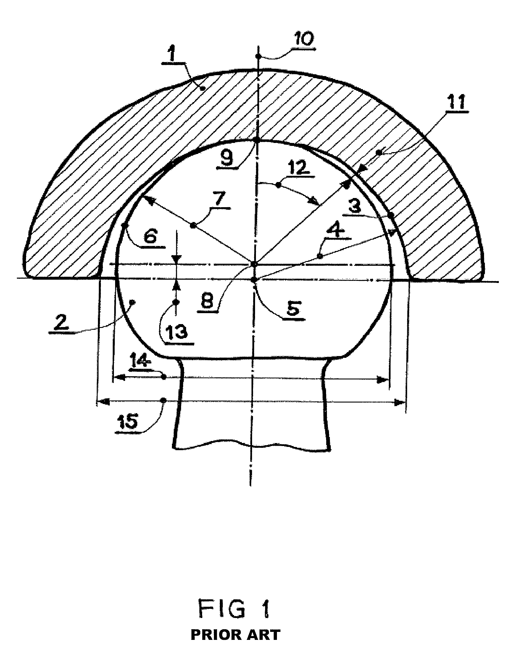
[0061]FIG. 1 is a schematic cross sectional view of the artificial hip joint articulation according to current standards.

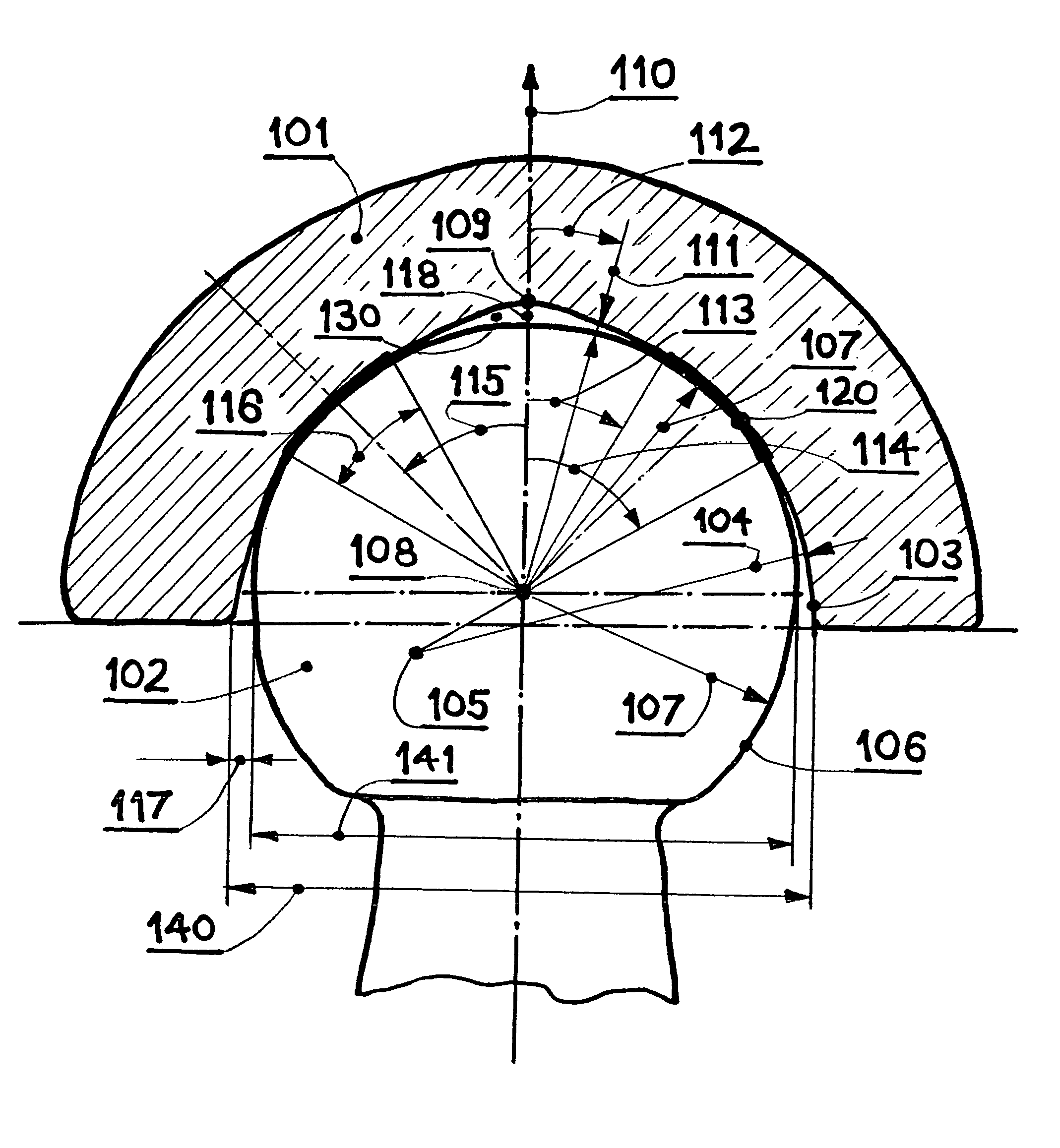
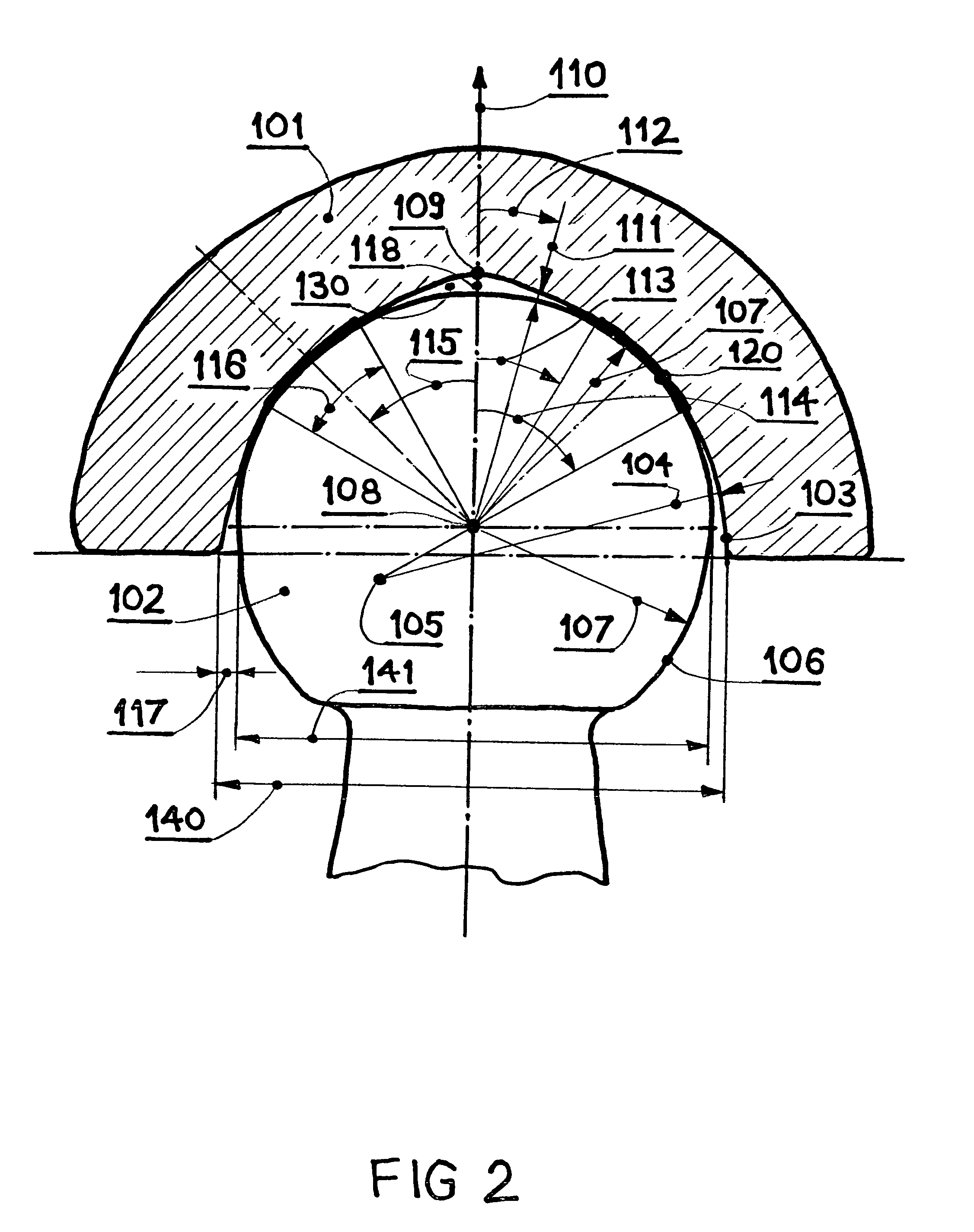
[0062]FIG. 2 is a schematic cross sectional view of the artificial total hip joint articulation according to the invention, showing a spherical head in an aspherical, fossa cup.

[0063]FIG. 2a is a perspective view showing a theoretical band of contact on a spherical surface;

[0064]FIG. 2b is a schematic view of theoretical surface contact over an arc of a spherical surface;

[0065]FIG. 3 is a schematic cross sectional view of the artificial total hip joint articulation according to the invention, showing an aspherical, fovea head in a spherical cup.

[0066]FIG. 4 is a cross sectional view of the artificial total hip joint according to the invention, showing a spherical head in an aspherical, fossa cup, whereby the axis of symmetry of the cup inner shape is offset from the main axis of the cup, so as to place the fossa of the cup into the window of major j...


PUM


Abstract

The invention reduces wear in total joint articulations by modifications of the shape of either component of the kinematic pair, so as to result in an annular surface contact between the two components. Fluid trapped between the two components within the inner contour of the annular contact area is pressurized under load due to elastic deformation of the components and exuded out through inter-articular gap over the surface of contact, aiding in lubrication and reducing the wear. Reduced to practice for a total hip joint with UHMWPE-metal pair, the wear rate tested in a hip joint simulator up to five million cycles was reduced by factor seven to fifteen compared to conventionally shaped components.

Description

CROSS REFERENCE TO RELATED APPLICATION[0001]This application is a 35 U.S.C. 371 National Phase Entry Application from PCT / EP2007 / 009944, filed Nov. 16, 2007, which claims the benefit of U.S. Provisional Application No. 60 / 859,491 filed on Nov. 17, 2006, the disclosure of which is incorporated herein in its entirety by reference.FIELD OF THE INVENTION[0002]The invention relates to means of reducing wear in total joint replacements. Wear of Ultra High Molecular Weight Polyethylene (UHMWPE), still the most commonly used articulation material, is considered a major factor contributing to aseptic loosening and thus limiting the duration of artificial joints. Reduction of UHMWPE wear has been an important topic of research and development from the sixties with the increased urgency accorded to the problem in the last decade. Metal-metal combination produces less, but nevertheless, biologically, significant wear. Potential toxicity of metal ions is both, a major concern and a motivation to...

Claims


Application Information

Patent Timeline
Patent Type & Authority Patents(United States)
IPC IPC(8): A61F2/28A61F2/30
CPCA61F2/32A61F2/38A61F2/4425A61F2/30A61F2/36A61F2/3804A61F2/3859A61F2/389A61F2/40A61F2/4202A61F2/4241A61F2/4261A61F2/468A61F2002/30321A61F2002/30617A61F2002/30673A61F2002/30685A61F2002/30827A61F2002/30838A61F2002/30934A61F2002/30955A61F2002/30957A61F2002/3225A61F2002/3493A61F2002/3496A61F2002/3498A61F2002/3623A61F2002/3625A61F2002/365A61F2002/443A61F2250/0025A61F2250/0097A61F2310/00011A61F2310/00179A61F2002/30657A61F2002/30655
Inventor TEPIC, SLOBODAN
Owner SCYON ORTHOPAEDICS
Learn More