Supercharge Your Innovation With Domain-Expert AI Agents!

Data transfer device and electronic camera

a technology of electronic camera and data transfer device, which is applied in the direction of digital transmission, picture signal generator, television system, etc., can solve the problems of complicated configuration, time-consuming, cost-related problems, etc., and achieve the effect of simple configuration

Active Publication Date: 2012-12-04
NIKON CORP
View PDF2 Cites 1 Cited by
  • Summary
  • Abstract
  • Description
  • Claims
  • Application Information

AI Technical Summary

Benefits of technology

The patent text describes a data transfer device that allows for easy adjustment of a clock signal to synchronize with a digital data signal. The device includes a decision unit and a phase adjusting unit that work together to determine the amount of adjustment needed to shift the phase of the clock signal. This adjustment is used to transfer the data signal in synchronization with the clock signal. The technical effect of this invention is to enable quick and simple synchronization of clock signals and data signals in a data transfer device.

Problems solved by technology

In order to deal with such a problem, it is conceivable to previously perform a calculation of the transmission path using information and to reflect the calculation result on an A / W of a mount substrate, but, it takes time and there is a problem in terms of cost.
However, in the above application, the configuration is complicated and it requires time for the adjustment.

Method used


Image

  • Data transfer device and electronic camera
  • Data transfer device and electronic camera
  • Data transfer device and electronic camera

Examples


Embodiment Construction

[0035]

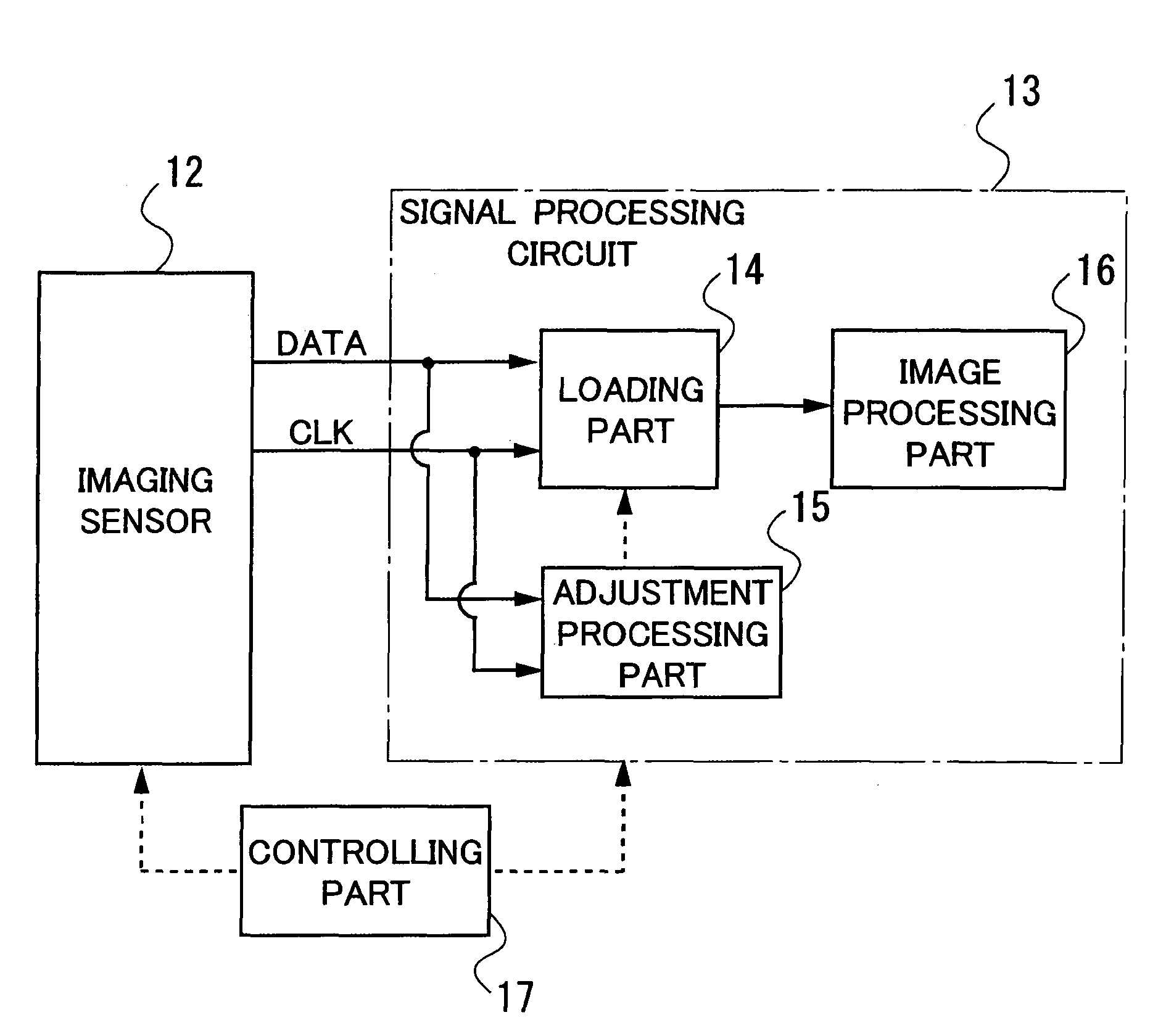
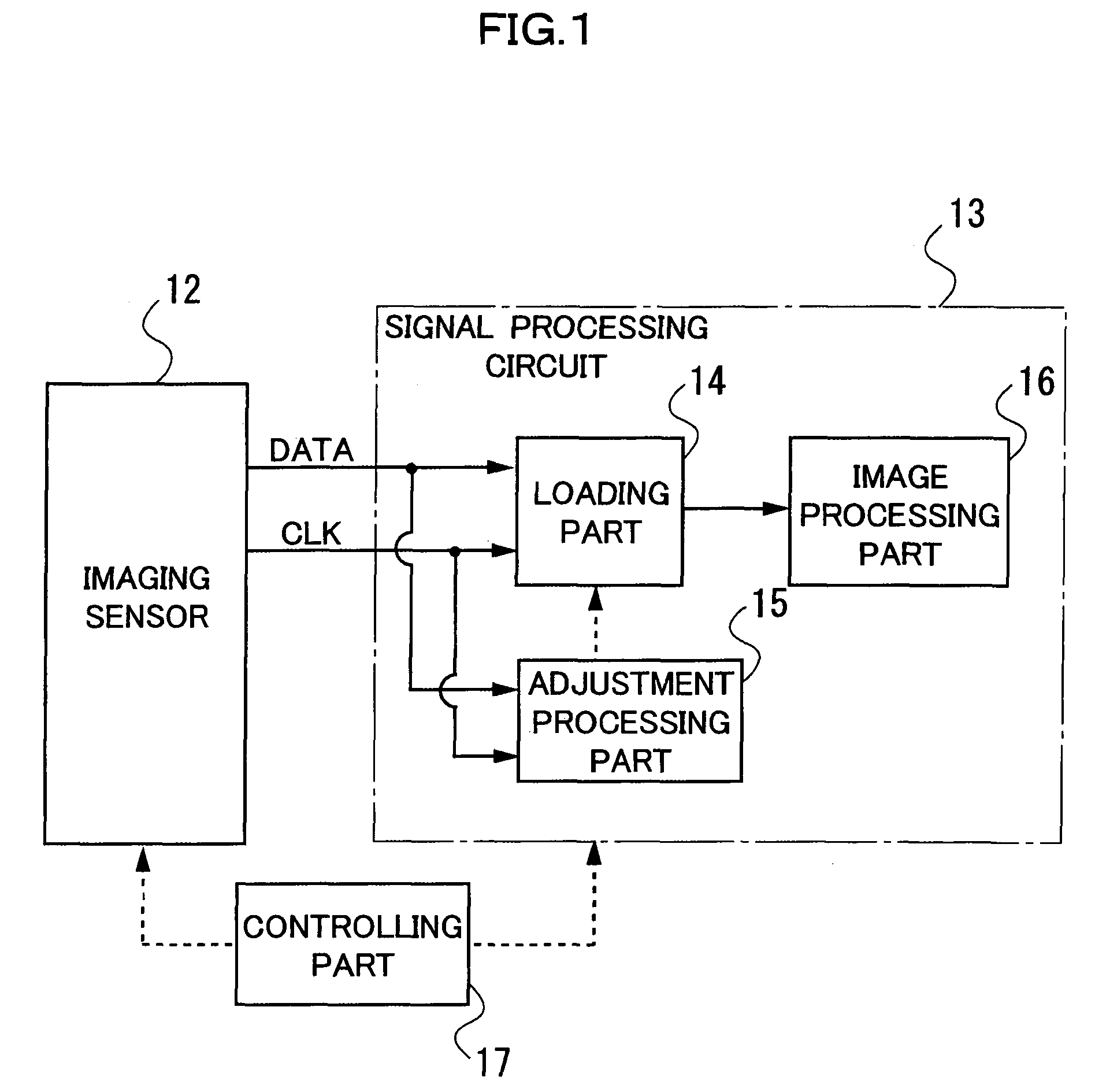
[0036]FIG. 1 is a schematic view showing a configuration example of a data transfer device according to one embodiment. FIG. 1 shows the configuration example when an imaging sensor 12 of an electronic camera is set as an output device and a signal processing circuit 13 of the electronic camera is set as an input device.

[0037]The imaging sensor 12 of the one embodiment has a light-receiving surface on which a plurality of light-receiving elements are two-dimensionally arranged, and outputs an image signal of a subject image which is image-formed on the light-receiving surface with an imaging optical system (not shown). Further, the imaging sensor 12 has an A / D conversion circuit (not shown) on a chip, and a digital data signal is output from an output terminal of the imaging sensor 12.

[0038]Here, to the imaging sensor 12 of the one embodiment, one ends of a plurality of signal lines which serially transfer image signals (details will be described later) and one end of a signal...


PUM


Abstract

A data transfer device can adjust a phase of a clock signal with a simple configuration in a short period of time when transferring a digital data signal in synchronization with the clock signal. Accordingly, the data transfer device includes a data transfer line serially transferring the data signal, a clock transfer line transferring the clock signal, a decision unit deciding an adjustment amount by which the phase of the clock signal accompanying the data signal is shifted, the adjustment amount being used when transferring the data signal in synchronization with the clock signal, and a phase adjusting unit shifting the phase of the clock signal in accordance with the adjustment amount decided by the decision unit while keeping a frequency of the clock signal fixed.

Description

CROSS REFERENCE TO THE RELATED APPLICATIONS[0001]This application is based upon and claims the benefit of priority from Japanese Patent Application No. 2007-334514, filed on Dec. 26, 2007, the entire contents of which are incorporated herein by reference.BACKGROUND[0002]1. Field[0003]The present application relates to a data transfer device suitable for transferring digital data in high speed between electronic devices or between semiconductor elements and peripheral techniques of the data transfer device.[0004]2. Description of the Related Art[0005]Conventionally, it has been required to speed up a transfer of digital data. As a more secure and safer scheme, a data transfer of serial transmission scheme has been widely adopted. In this serial transmission scheme, a clock signal to be a reference for the transmission is transmitted, as a carrier wave, simultaneously with digital data, thereby enhancing a reliability of the data transfer.[0006]However, in general, when the clock sign...

Claims


Application Information

Patent Timeline
Patent Type & Authority Patents(United States)
IPC IPC(8): H04N5/225
CPCH03L7/0814H04L7/0037H04L7/0337H04L7/0008H04L7/046
Inventor MORISHITA, AKIHIKO
Owner NIKON CORP
Features
  • R&D
  • Intellectual Property
  • Life Sciences
  • Materials
  • Tech Scout
  • Unparalleled Data Quality
  • Higher Quality Content
  • 60% Fewer Hallucinations
Learn More