

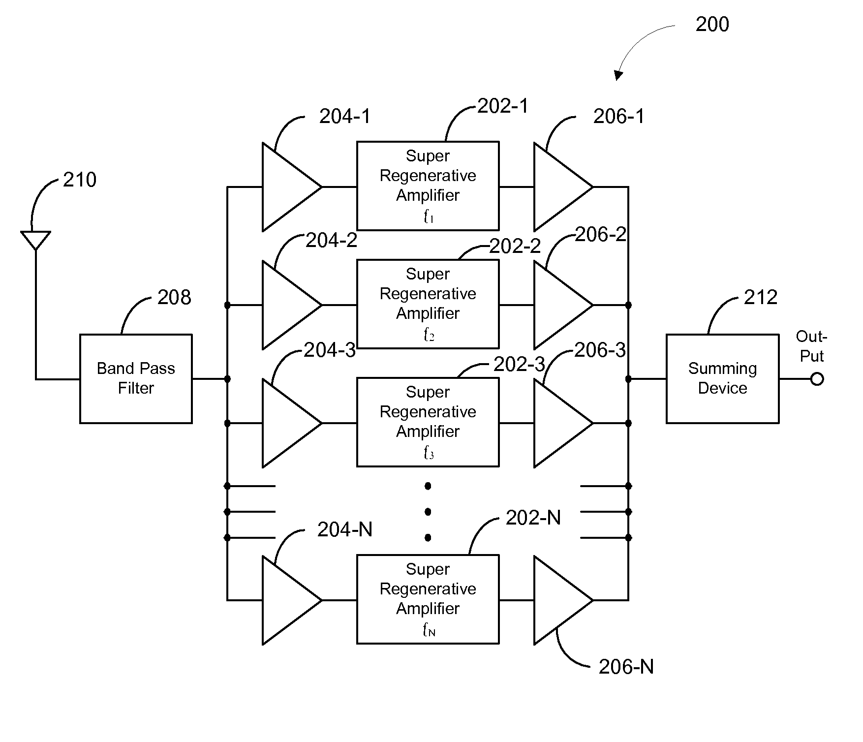
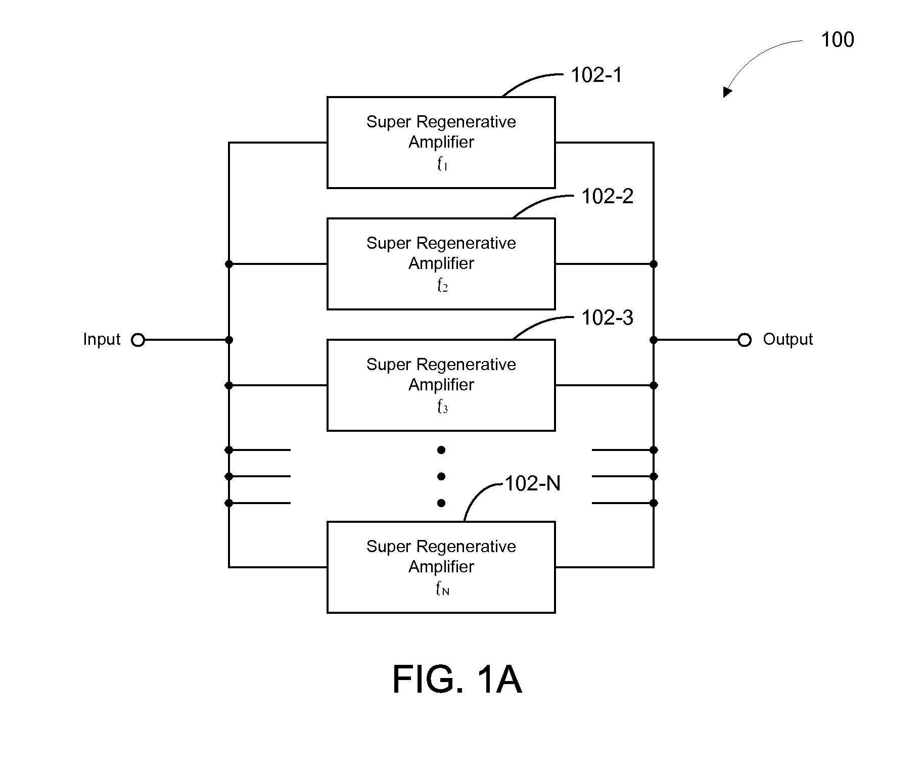
Super regenerative (SR) apparatus having plurality of parallel SR amplifiers tuned to distinct frequencies
a super regenerative and parallel technology, applied in the field of communication systems, can solve the problems of inability to reject out-of-band jamming signals, undesirable receiver architecture, and one or more cascaded linear amplifiers, and achieve the effect of preventing power leakag
- Summary
- Abstract
- Description
- Claims
- Application Information
AI Technical Summary
Benefits of technology
Problems solved by technology
Method used
Image

Examples
Embodiment Construction
[0023]Various aspects of the disclosure are described below. It should be apparent that the teachings herein may be embodied in a wide variety of forms and that any specific structure, function, or both being disclosed herein are merely representative. Based on the teachings herein one skilled in the art should appreciate that an aspect disclosed herein may be implemented independently of any other aspects and that two or more of these aspects may be combined in various ways. For example, an apparatus may be implemented or a method may be practiced using any number of the aspects set forth herein. In addition, such an apparatus may be implemented or such a method may be practiced using other structure, functionality, or structure and functionality in addition to or other than one or more of the aspects set forth herein.
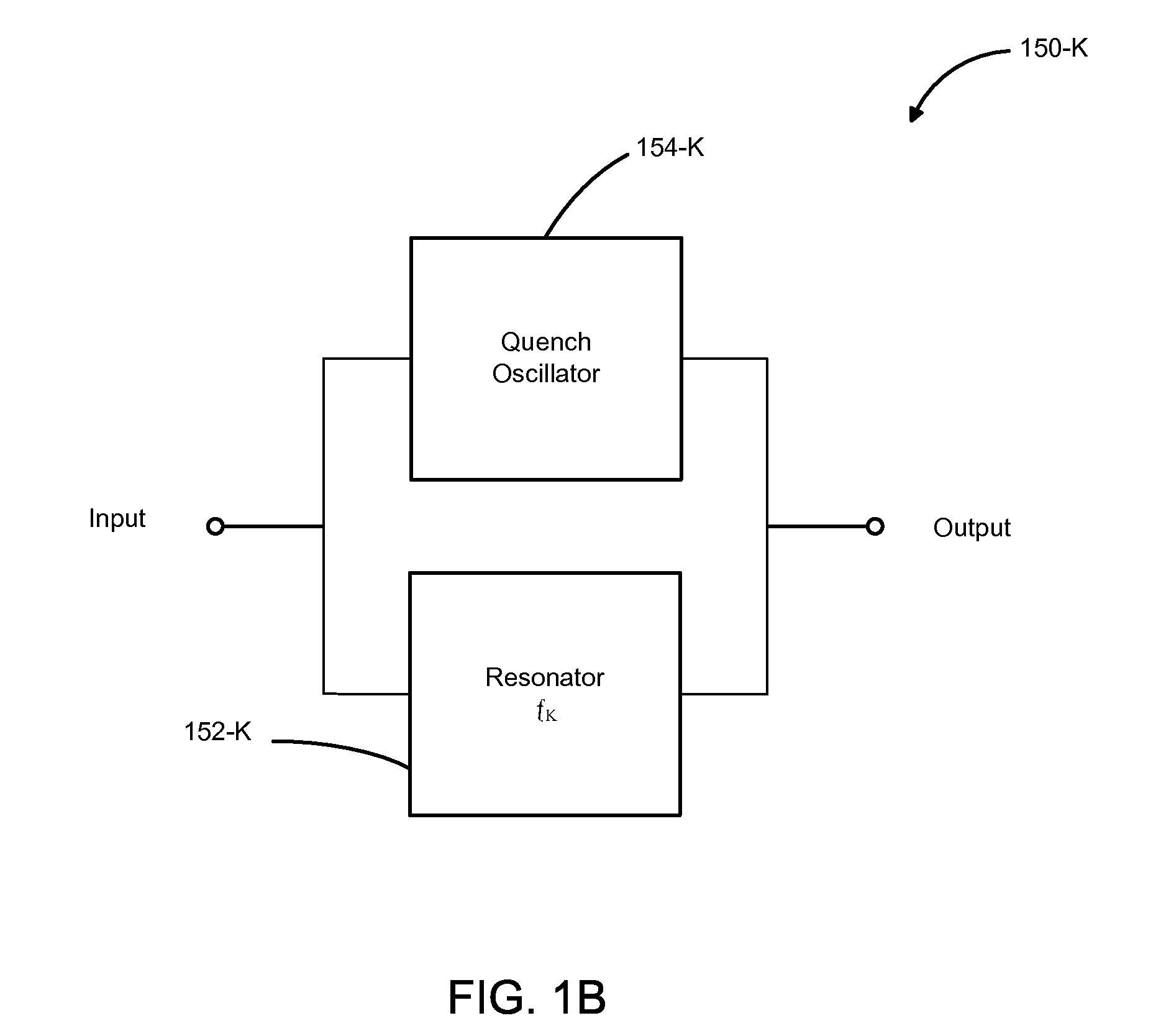
[0024]As an example of some of the above concepts, in some aspects, the apparatus may comprise a plurality of super regenerative (SR) amplifiers (also referred to as ...
PUM
 Abstract
Description
Claims
Application Information