Method and apparatus for fluid migration profiling

a fluid migration and profiling technology, applied in the direction of nuclear radiation detection, well-logging, electric/magnetic detection, etc., can solve the problems of slow stepwise monitoring of well depth, inability to generate revenue, and cost millions of dollars per well to fix the problem

Active Publication Date: 2012-12-04
HIFI ENG
View PDF15 Cites 7 Cited by
  • Summary
  • Abstract
  • Description
  • Claims
  • Application Information

AI Technical Summary

Problems solved by technology

This path can be due to fractures around the wellbore, fractures in the production tubing, poor casing to cement / cement to formation bond, channeling in the cement, or various other reasons.
These may be quite violent, producing an acoustic signal that is felt on the surface, or at a significant distance from the source.
The repair of these situations does not generate revenue for the gas company, and can cost millions of dollars per well to fix the problem.
This serial, stepwise monitoring of well depths is slow—a typical well may take 6-12 hours to log.
Additionally, as the recording device is only recording data at each depth for one minute or thereabouts, the recording device may not be directly at the leak point when a noise anomaly occurs—for a well with a low leak rate, a noise anomaly may be missed altogether.
The length of the wire, and in the case of an analog signal, filtering and bandwidth limitations, also take a toll on the data by the time it is actually received uphole into the computer acquisition system, resulting in a poor signal to noise ratio.

Method used


Image

  • Method and apparatus for fluid migration profiling
  • Method and apparatus for fluid migration profiling
  • Method and apparatus for fluid migration profiling

Examples


examples

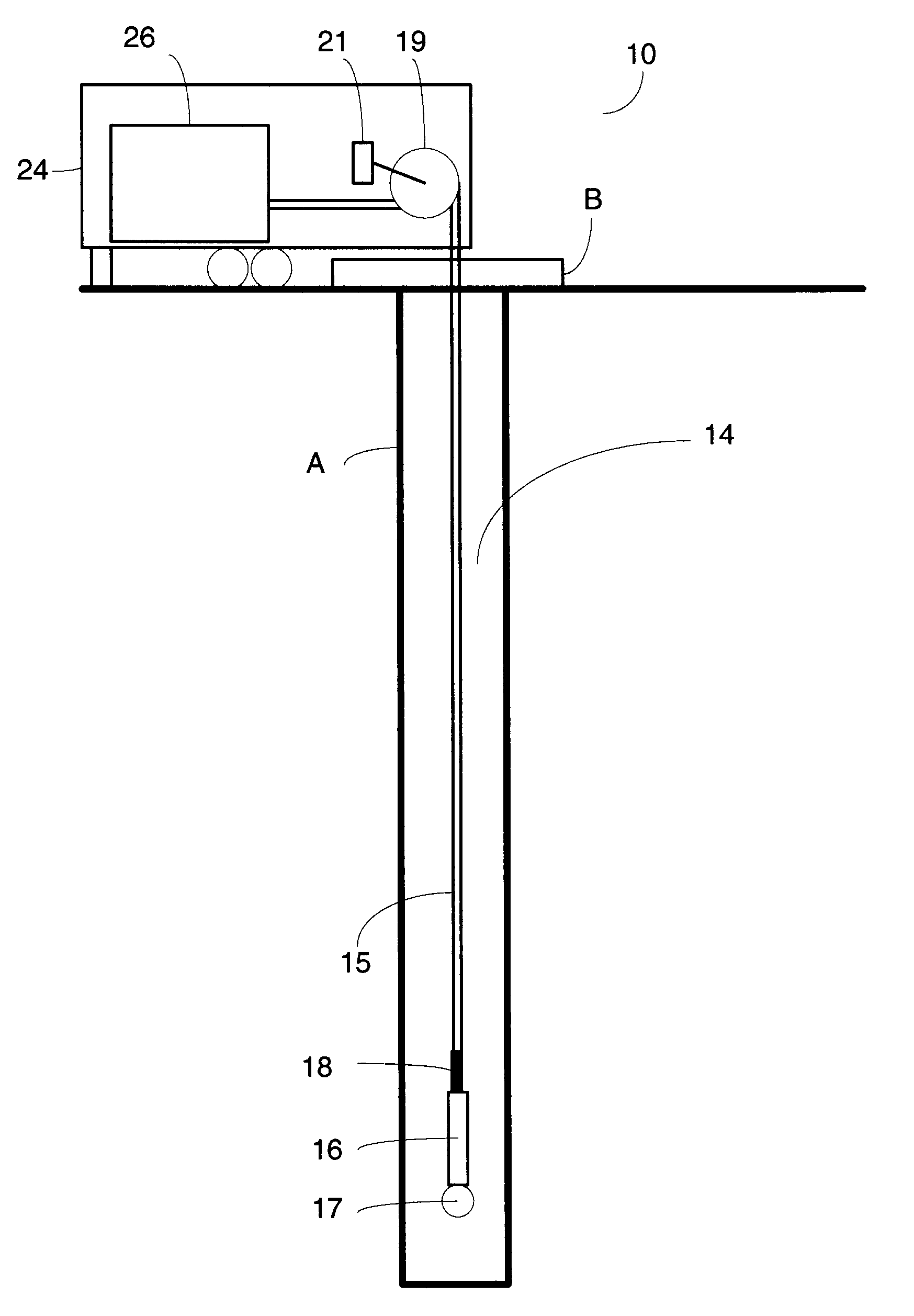
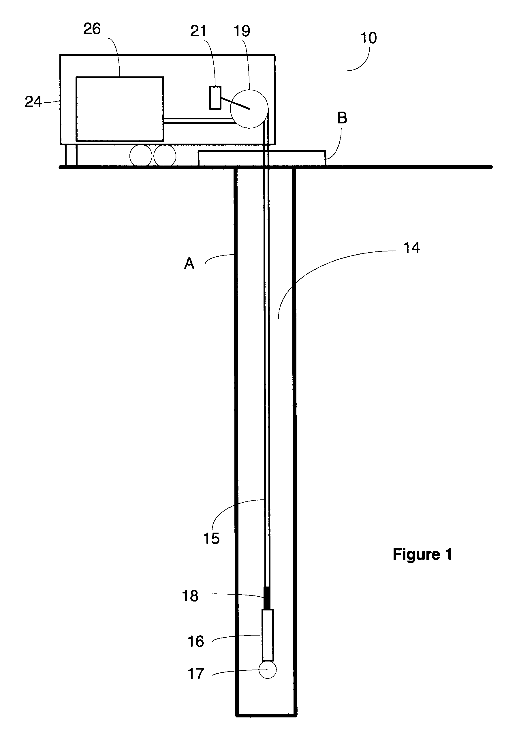
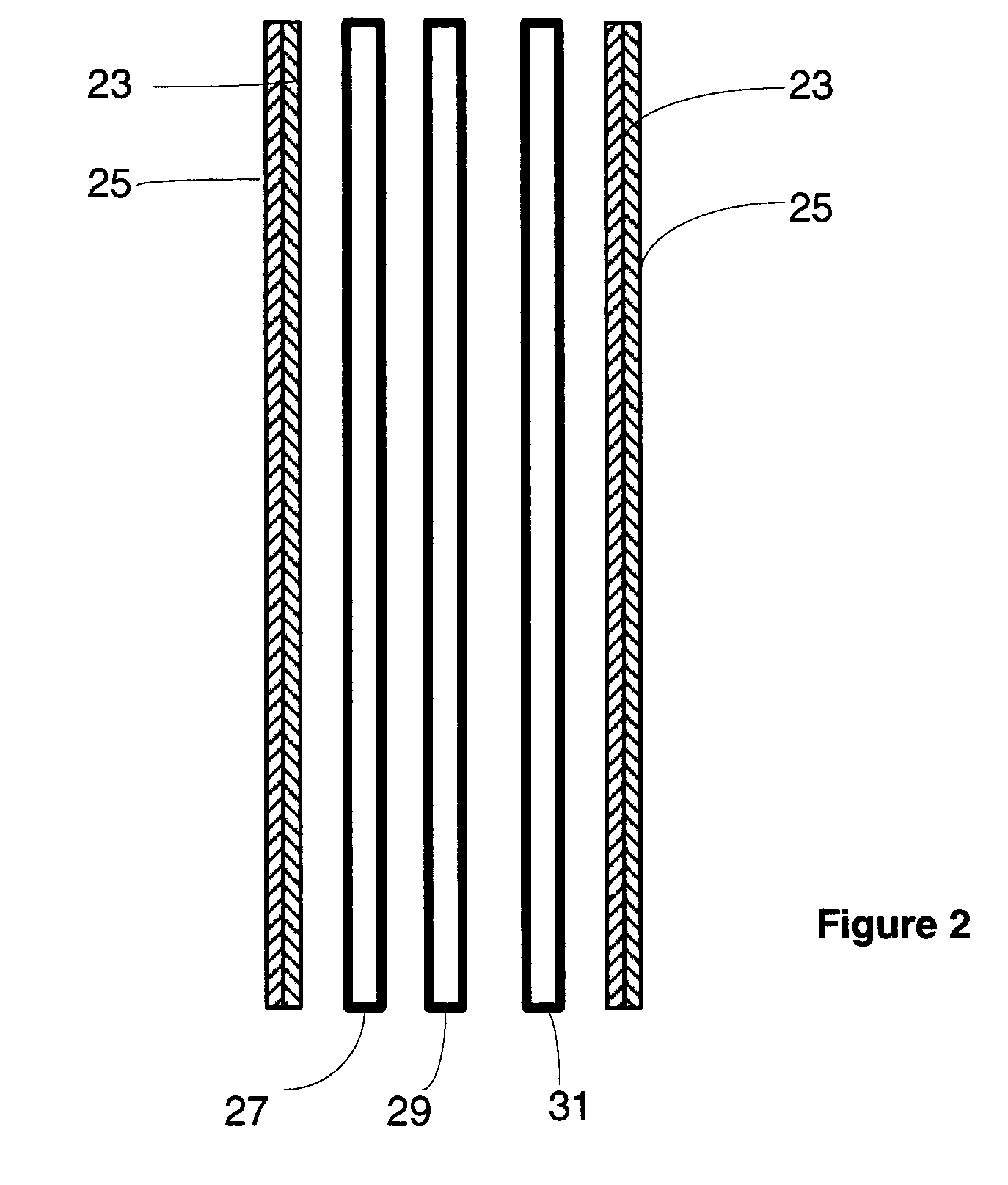
[0177]The performance of an array of two fiber-Bragg grating transducers (straight array) was compared with that of a transducer having a polyurethane core or mandrel of 60 A or 80 A durometer using a test well configured to simulate gas leaks at varying depths and flow rates. For both the straight array and the transducers with mandrel, 10 m of fiber optic cable separated the gratings. The test well comprised an outer casing extending from above the ground level to below the ground level, with a sealed end below ground. An inner casing in parallel and centered with the outer casing extends from the below ground end of the outer casing to above the ground level or higher. The above ground end of the inner casing is threaded to enable attachment of a union or valve, as desired. Two line pipes were used as a flow line, and for filling and / or accessing an annulus formed between the inner and outer casings. A series of six steel tubes, extending to 3 depths of the well annulus were arra...


PUM


Abstract

The method for obtaining a fluid migration profile for a wellbore, including the steps of obtaining a static profile for a logged region of the wellbore, obtaining a dynamic profile for the logged region of the wellbore, digitally filtering the dynamic profile to remove frequency elements represented in the static profile, to provide a fluid migration profile, and storing the fluid migration profile on a computer-readable memory.

Description

CROSS-REFERENCE TO RELATED APPLICATIONS[0001]This application is a 371 U.S. National Stage of International Application No. PCT / CA2008 / 000314, filed Feb. 12, 2008 and published in English as WO 2008 / 098380 A1 on Aug. 21, 2008. This application claims the benefit of U.S. Provisional Application No. 60 / 901,299, filed Feb. 15, 2007. The disclosures of the above applications are entirely incorporated herein by reference.FIELD OF INVENTION[0002]The present invention relates to methods for profiling fluid migration in oil or gas wells.BACKGROUND OF THE INVENTION[0003]Casing vent flow / gas migration (CVF / GM) analysis is becoming a major concern for oil / gas producers around the world. In order for the gas to negotiate itself from the source to surface, a path must be present. This path can be due to fractures around the wellbore, fractures in the production tubing, poor casing to cement / cement to formation bond, channeling in the cement, or various other reasons.[0004]Well logging is perform...

Claims


Application Information

Patent Timeline
Patent Type & Authority Patents(United States)
IPC IPC(8): G01V1/40G01V3/00G01V5/00E21B47/135
CPCE21B47/123E21B47/1005E21B47/103E21B47/135
Inventor HULL, JOHNKRAMER, HERMANN
Owner HIFI ENG
Why Eureka
Try Eureka