Control device, image forming device, wear detecting method, program, and storage device

a control device and image forming technology, applied in the direction of motor/generator/converter stopper, dynamo-electric converter control, gearing, etc., can solve the problem of large variation in the surface speed of the intermediate transferring belt, the wear of gears can be detected, and the control of the variation of the surface speed in a short time is difficul

Inactive Publication Date: 2012-12-04
RICOH KK
View PDF8 Cites 7 Cited by
  • Summary
  • Abstract
  • Description
  • Claims
  • Application Information

AI Technical Summary

Benefits of technology

[0010]Accordingly, the Embodiments of the present invention provide a novel and useful control device, an image forming device, a wear detecting method, a program, and a storage device which can early detect wear of gears transmitting the rotation of a motor, solving one or more of the problems discussed above.

Problems solved by technology

However, it is known that control of variation of a surface speed (for example, a range of several hundreds Hz) generated within a short time is difficult.
For example, when the gear is excessively worn, a gap between a cog of the gear and a cog of another gear becomes large to cause large variation in the surface speed of the intermediate transferring belt.
However, there is a problem in the image forming device of Japanese Unexamined Patent Application Publication No. 2005-221577 that wear of gears can be detected only in a case where the gear is excessively worn and lacks a cog.
For example, it is impossible to detect the extent of variation of the surface speed caused by a slightly worn gear.
Further, gears are not worn to the extent of affecting image quality when a material of the gears is properly selected.
However, the need to have high image quality has no limits, and there are many cases where further high speed and a large amount of printing are required.
Further, wear of the gears is apt to occur as the rotational speed of the gears increases.
With respect to the need, if wear cannot be detected after a gear is excessively worn, printed materials continue to be output with gradually decreasing image quality, and a print obviously having wrong (abnormal) image quality is obtained when the wear is detected.

Method used


Image

  • Control device, image forming device, wear detecting method, program, and storage device
  • Control device, image forming device, wear detecting method, program, and storage device
  • Control device, image forming device, wear detecting method, program, and storage device

Examples


embodiment 1

Summary of Wear Detection

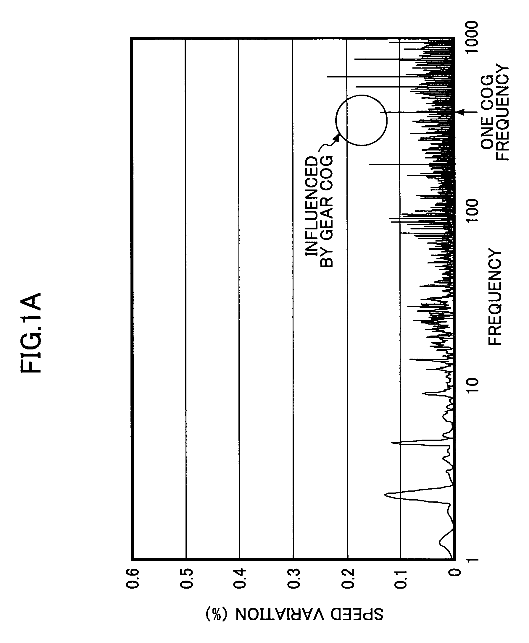
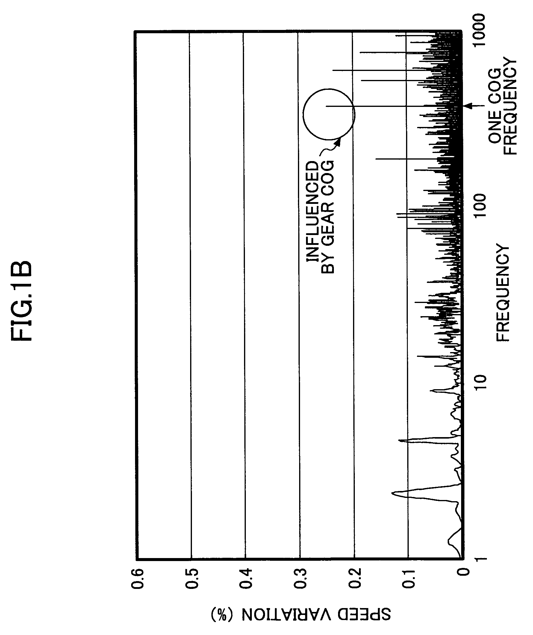
[0043]FIG. 1A and FIG. 1B are graphs illustrating the speed variation of a driving roller 16 with respect to frequency. FIG. 1A illustrates the speed variation when cogs of a gear are not worn. FIG. 1B illustrates the speed variation when cogs of a gear are slightly worn. As described in detail later, FIGS. 1A and 1B are obtained by applying a fast Fourier transform to a signal of the rotational speed of the driving roller 16, which supports an intermediate transferring belt 14. Hereinafter, speed variations with respect to the frequency band illustrated in FIGS. 1A and 1B are the results of applying the fast Fourier transform (FFT). In order to form an image having high image quality, it is preferable to limit the speed variation to be a predetermined value or less (e.g. 0.25% or less) along an entire frequency range.

[0044]Since the speed variation is caused every one or two rotations of a roller supporting an intermediate transferring belt 14 due to eccent...

embodiment 2

[0108]In Embodiment 1, the control of the primary transferring motor in the wear detection mode has not been referred to. However, by appropriately controlling the primary transferring motor 41, it becomes possible to make the speed variation clearly emerge even though only slight wear enabling detection of the predictor of wear exists.

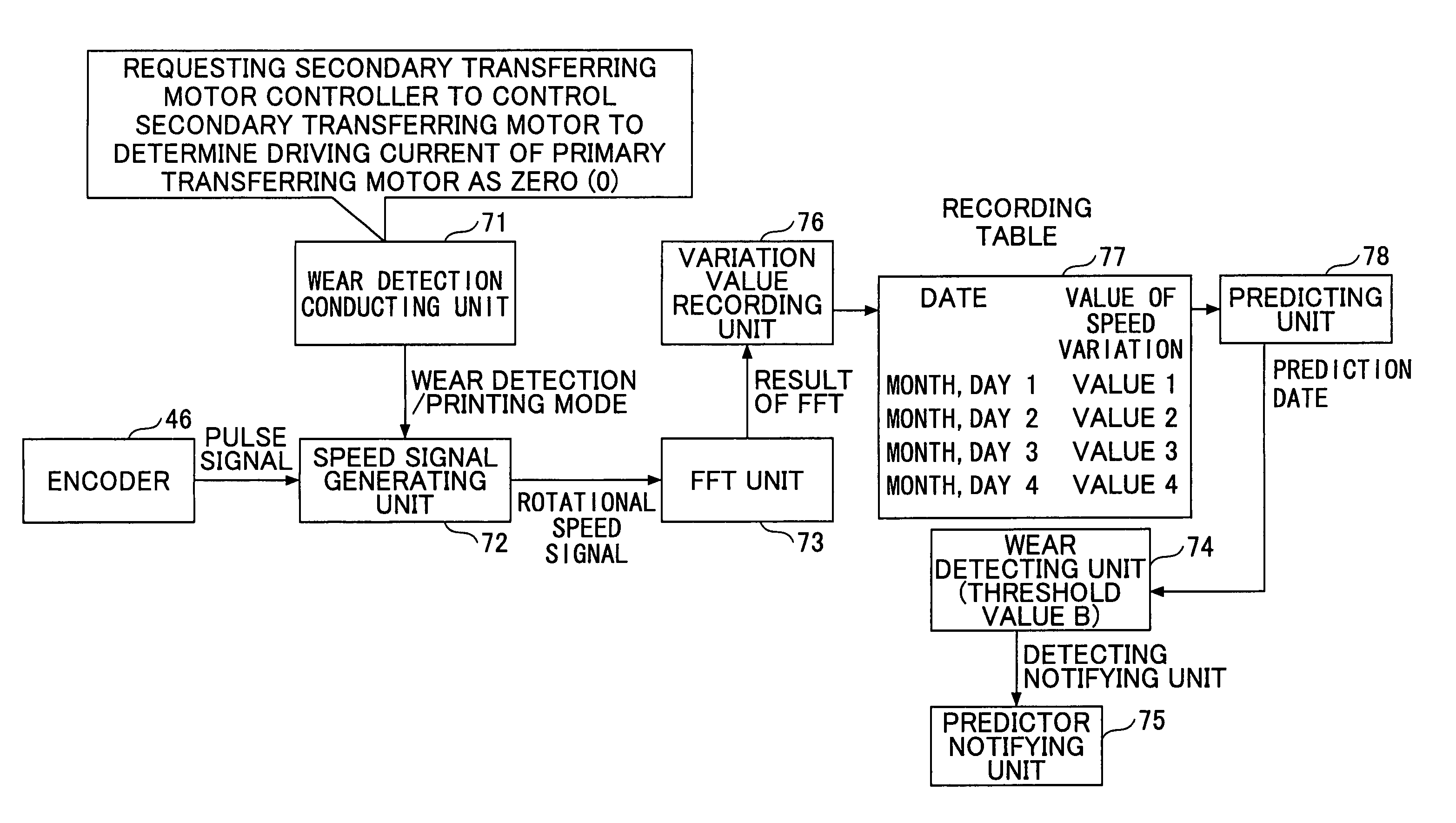
[0109]Next, there is described control device 200 for controlling a rotational speed of the primary transferring motor 41 so that speed variation at one cog frequency is amplified in the image forming device 100 of Embodiment 1. In Embodiment 2, such control is referred to as “amplifying control”. In the amplifying control, a motor driving circuit 54 controls the rotational speed of a secondary transferring motor 42 so that an electric current of the primary transferring motor 41 becomes zero (0). In a manner similar to Embodiment 1, the speed variation is detected for the frequency band, to thereby detect the predictor of wear of the gears 43a and 43...


PUM


Abstract

A control device includes a transmission unit including a first gear rotating with a motor shaft and a second gear rotating with a rotating roller which drives a rotated body, a speed detecting unit for detecting the rotational speed of the rotated body or rotating roller, a motor controlling unit for maintaining a constant motor shaft rotational speed based on the rotational speed, a converting unit for converting the rotational speed to a relationship between a frequency contained in a variation of the rotational speed in association with time and a variation value of the rotational speed, and a wear detecting unit for detecting a predictor of wear of cogs in at least one of the first and second gears when the variation value at a specified frequency, determined based on the number of the cogs of the first gear and the motor shaft rotational speed, exceeds a threshold value.

Description

BACKGROUND OF THE INVENTION[0001]1. Field of the Invention[0002]The present invention generally relates to control device, an image forming device, a wear detecting method, a program, and a storage device, which enable early detection of wear of gears transmitting the rotation of a motor.[0003]2. Description of the Related Art[0004]In order to form an image having high image quality, an image forming device employs various measures. One of the measures is controlling a surface speed of an intermediate transferring belt to have a constant surface speed. When the surface speed varies while forming an image on one sheet of paper, image deformation, uneven shading, a color shift and so on are apt to occur. Therefore, there is a technique of controlling a motor such that the surface speed of the intermediate transferring belt is detected by an encoder or the like and the intermediate transferring belt may have a constant speed, as, for example, in Japanese Unexamined Patent Application P...

Claims


Application Information

Patent Timeline
Patent Type & Authority Patents(United States)
IPC IPC(8): G01B3/44F16H1/06G01M99/00G03G21/00
CPCG05B23/0283
Inventor ISHIZAKI, YUUSUKEKOIKE, TAKAHISA
Owner RICOH KK
Why Eureka
Try Eureka