
Plastic nut for ball screw and method for manufacturing same

a technology of ball screw and nut, which is applied in the direction of threaded fasteners, gearing, hoisting equipment, etc., can solve the problems of increasing manufacturing costs, expensive cutting tools, and normal cutting tools that wear out relatively quickly, and achieves high dimensional precision and early wear.

Active Publication Date: 2018-08-14
KURODA PRECISION INDS
View PDF7 Cites 0 Cited by
  • Summary
  • Abstract
  • Description
  • Claims
  • Application Information

AI Technical Summary

Benefits of technology

[0024]According to the plastic nut for a ball screw and the method for manufacturing the same of the present invention, because the screw thread groove is ground until the fibers in the matrix plastic are exposed on the surface of the screw thread groove, an early wear can be avoided, and a high dimensional precision can be maintained over an extended period of time.

Problems solved by technology

However, when machining a screw thread, the presence of reinforcing fibers in the material causes a normal cutting tool to wear out relatively quickly.
Therefore, an expensive cutting tool such as a diamond coated tool is required, and this causes an increase in the manufacturing cost.
Also, because fiber reinforced plastic has a higher thermal expansion coefficient than steel, the machining speed has to be controlled in order to avoid deformation due to the heat produced by the cutting process, and this further contributes to the increase in the manufacturing cost.
However, a thread formed by an injection molding process tends to wear out relatively quickly during the use in a feed screw mechanism, and a positional inaccuracy may be caused at a relatively early stage in use owing to the reduction in the dimensional precision of the thread.
Therefore, a feed screw nut made having a thread formed during an injection molding process may not be able to achieve a high dimensional precision that may be required.

Method used


Image

  • Plastic nut for ball screw and method for manufacturing same
  • Plastic nut for ball screw and method for manufacturing same
  • Plastic nut for ball screw and method for manufacturing same

Examples


Embodiment Construction

)

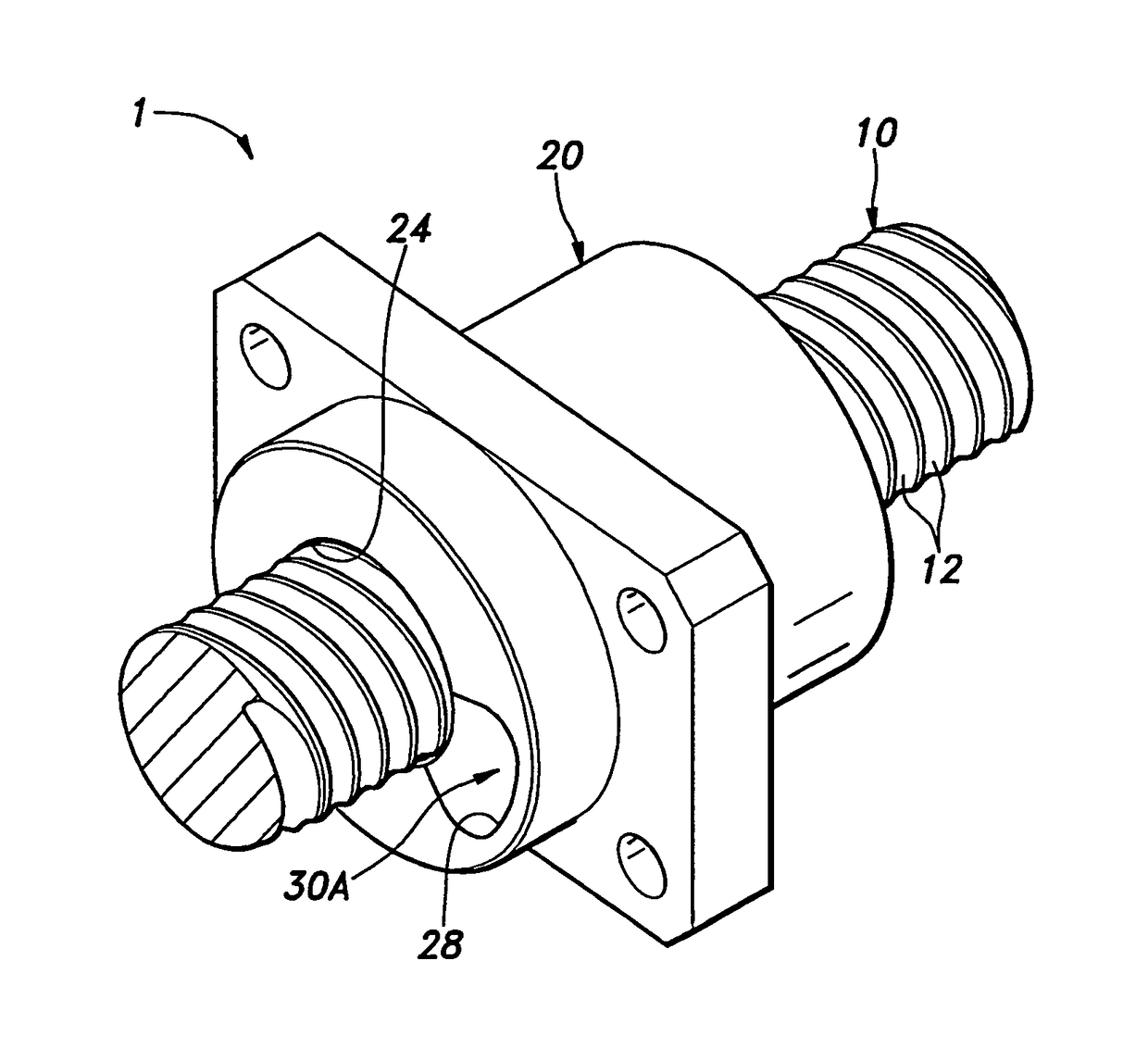
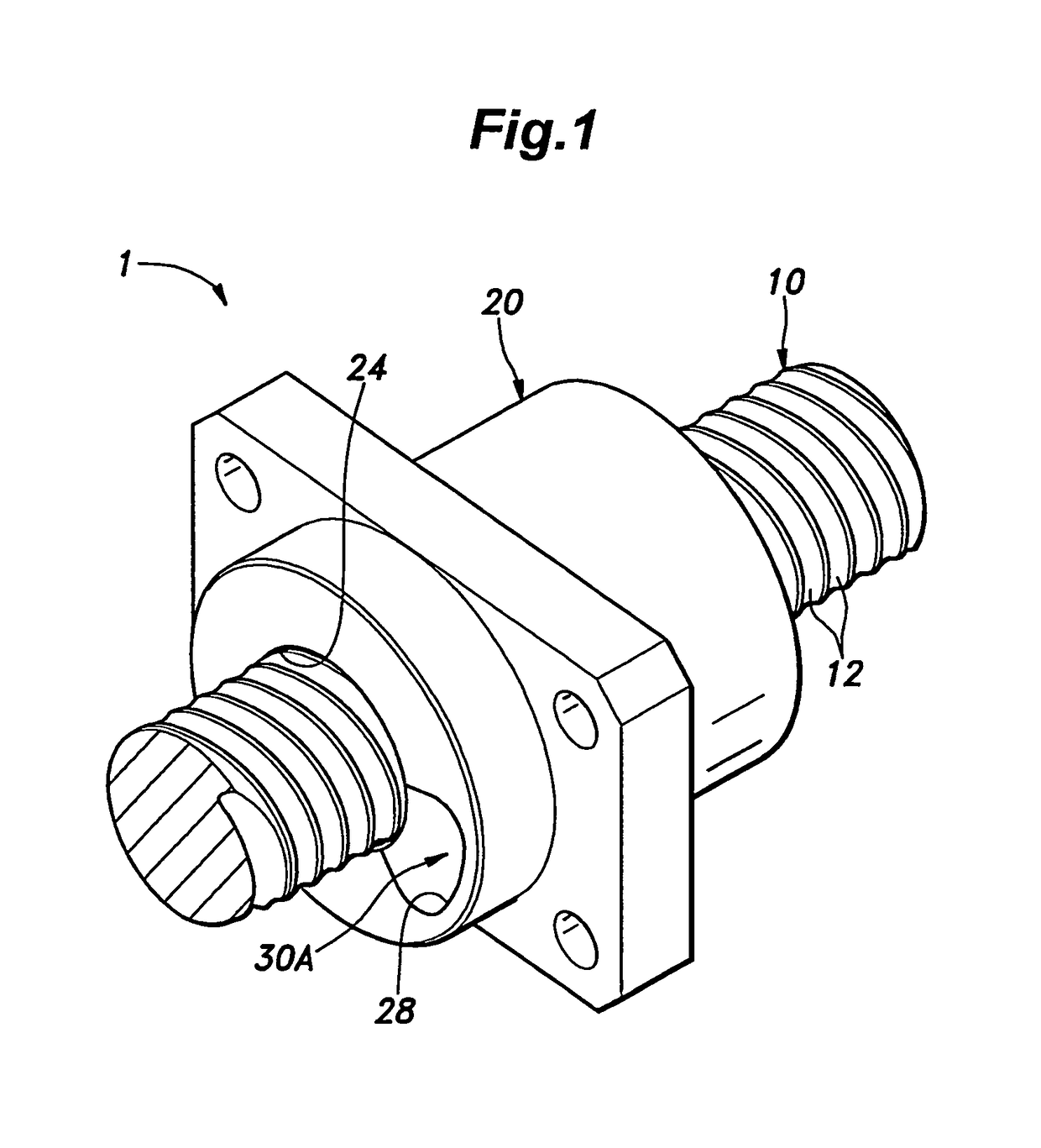
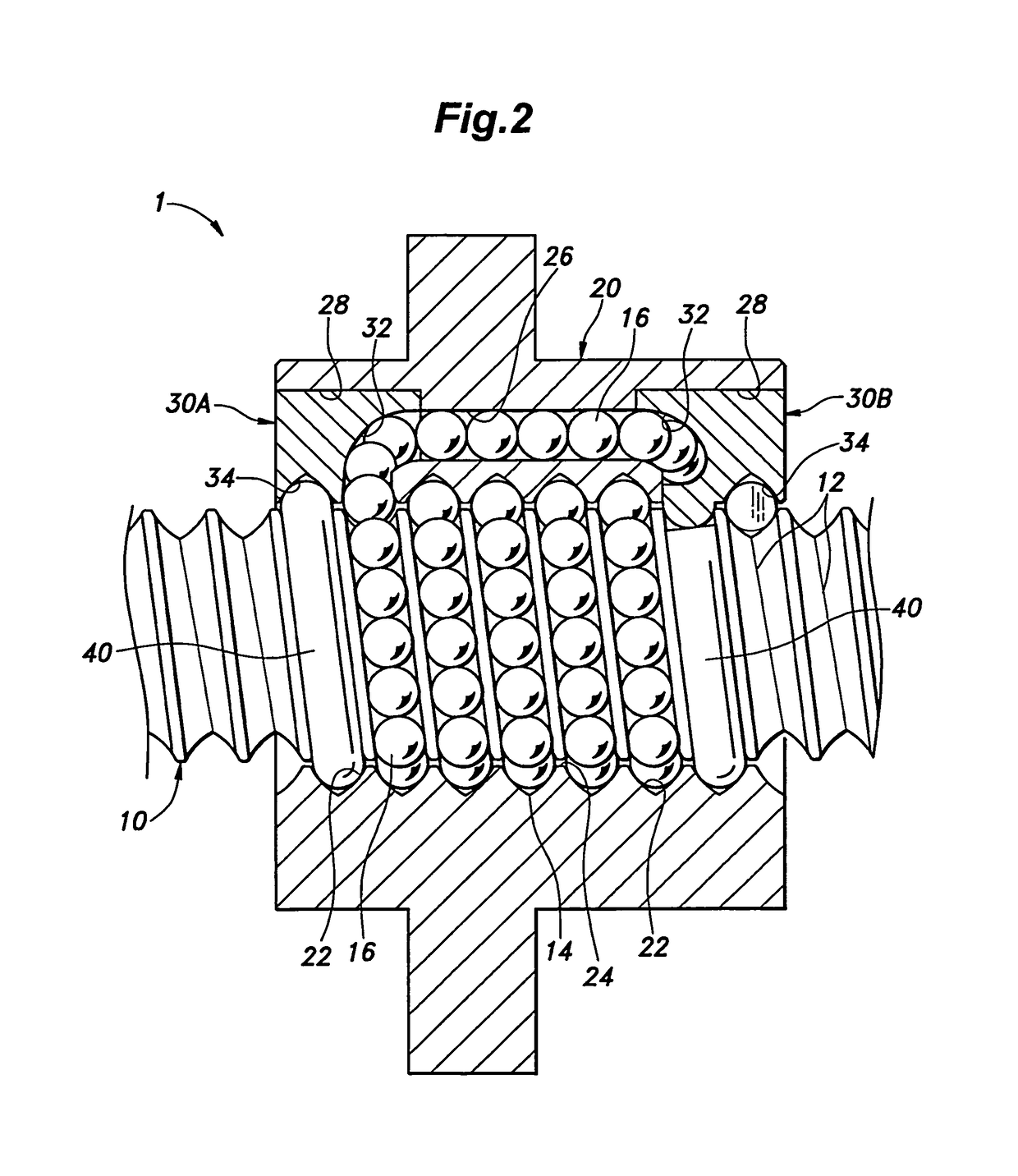
[0031]An embodiment of the ball screw in which the plastic nut is used is described in the following with reference to FIGS. 1 to 4.

[0032]As shown in FIGS. 1 and 2, a ball screw 1 includes a screw shaft 10 having a male screw thread groove 12 formed on the outer circumferential surface thereof, a nut (plastic nut for a ball screw) 20 defining a threaded bore 24 having a female screw thread groove 22 formed on the inner circumferential surface thereof and a pair of end deflectors 30A and 30B fitted to either axial end of the nut 20. The screw shaft 10 is made of roll formed stainless steel, the nut 20 is made of injection molded fiber reinforced plastic, and the end deflectors 30A and 30B are made of injection molded high polymer plastic such as POM (polyacetal resin) and PPS (polyphenylene sulfide resin).

[0033]Each end deflector 30A, 30B is fitted into a recess 28 formed in the corresponding axial end of the nut 20, and is fixedly secured therein by using an end deflector fixing me...


PUM

PropertyMeasurementUnit
lengthaaaaaaaaaa
diameteraaaaaaaaaa
thicknessaaaaaaaaaa

Abstract

In a plastic nut for a ball screw formed by injection molding fiber reinforced plastic, the reduction in precision over time due to wear is minimized. A thread groove is ground until the fibers in matrix plastic are exposed on the surface of the thread groove.

Description

TECHNICAL FIELD[0001]The present invention relates to a plastic nut for a ball screw and a method for manufacturing the same, and in particular to a plastic nut for a ball screw made by injection molding fiber reinforced plastic formed by mixing a reinforcing material consisting of fibers in matrix plastic and a method for manufacturing the same.BACKGROUND OF THE INVENTION[0002]As a nut for use in a feed screw mechanism, it is known to use a plastic nut made by injection molding fiber reinforced plastic formed by mixing whiskers in matrix plastic consisting of PPS (polyphenylene sulfide resin). See Patent Document 1, for instance. Such a nut for use in a feed screw mechanism can be made either by machining the screw thread therein or injection molding the screw thread therein.PRIOR ART DOCUMENTS(S)Patent Document(s)[0003]Patent Document 1: JP2001-116102ASUMMARY OF THE INVENTIONTask To Be Accomplished by the Invention[0004]A feed screw nut made of fiber reinforced plastic has a great...

Claims


Application Information

Patent Timeline
Patent Type & Authority Patents(United States)
IPC IPC(8): F16H1/24F16H25/24B24B19/02B29C45/17F16B37/00B29C45/00F16H55/02F16H25/22B29K81/00B29K105/12B29L1/00
CPCB29C45/0055B29C45/0005B29C45/178F16B37/00F16H25/24B24B19/022F16H2025/249B29C2045/0012B29C2045/0058B29K2081/04B29K2105/12B29K2905/12B29K2995/0012B29L2001/005F16H25/2214B29C45/0053
Inventor IWASAKI, YOSHIMI
Owner KURODA PRECISION INDS
Learn More