Golf club head

a technology of golf club head and ball head, which is applied in the field of golf club head, can solve the problems of difficult to realize both spin performance and resistance to ball damage, the ball may change the trajectory of the ball, and the ball is apt to be damaged, so as to achieve the effect of suppressing the ball damage and spin performan

Active Publication Date: 2012-12-11
SUMITOMO RUBBER IND LTD
View PDF16 Cites 194 Cited by
  • Summary
  • Abstract
  • Description
  • Claims
  • Application Information

AI Technical Summary

Benefits of technology

[0014]It is an object of the present invention to provide a golf club capable of enhancing the spin performance while suppressing the damage of the ball.
[0026]Both the suppression of the damage of the ball and the spin performance can be realized.

Problems solved by technology

On the other hand, when the edge is excessively sharp, the ball is apt to be damaged.
It is difficult to realize both the spin performance and resistance to the damage of the ball.
The damage of the ball may change a ball trajectory.
The damage of the ball may influence the spin rate.
The damage of the ball complicates the control of the hitting ball.

Method used


Image

  • Golf club head
  • Golf club head
  • Golf club head

Examples


example 1

[0171]A head of PW (pitching wedge) of “SRIXON ZR-700” (trade name) manufactured by SRI Sports Limited was used. The step (A) and the step (B) were carried out on the head to form face lines. The step (A) was carried out in the embodiment shown in FIG. 11 using the same cutter as the cutter 12. ACNC processing machine was used in the step (A). Next, the step (B) (plane cut processing) was carried out. The CNC processing machine was used in the step (B). The real loft angle of the head was 46 degrees.

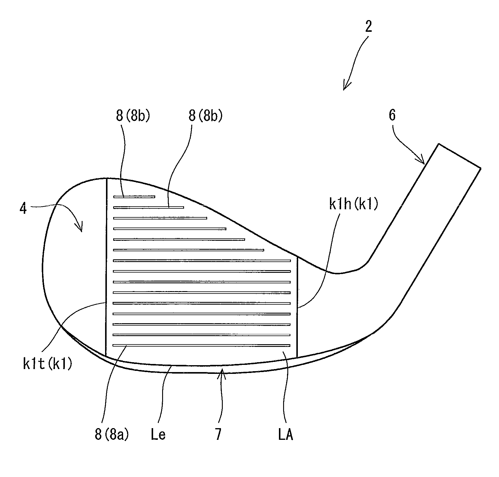
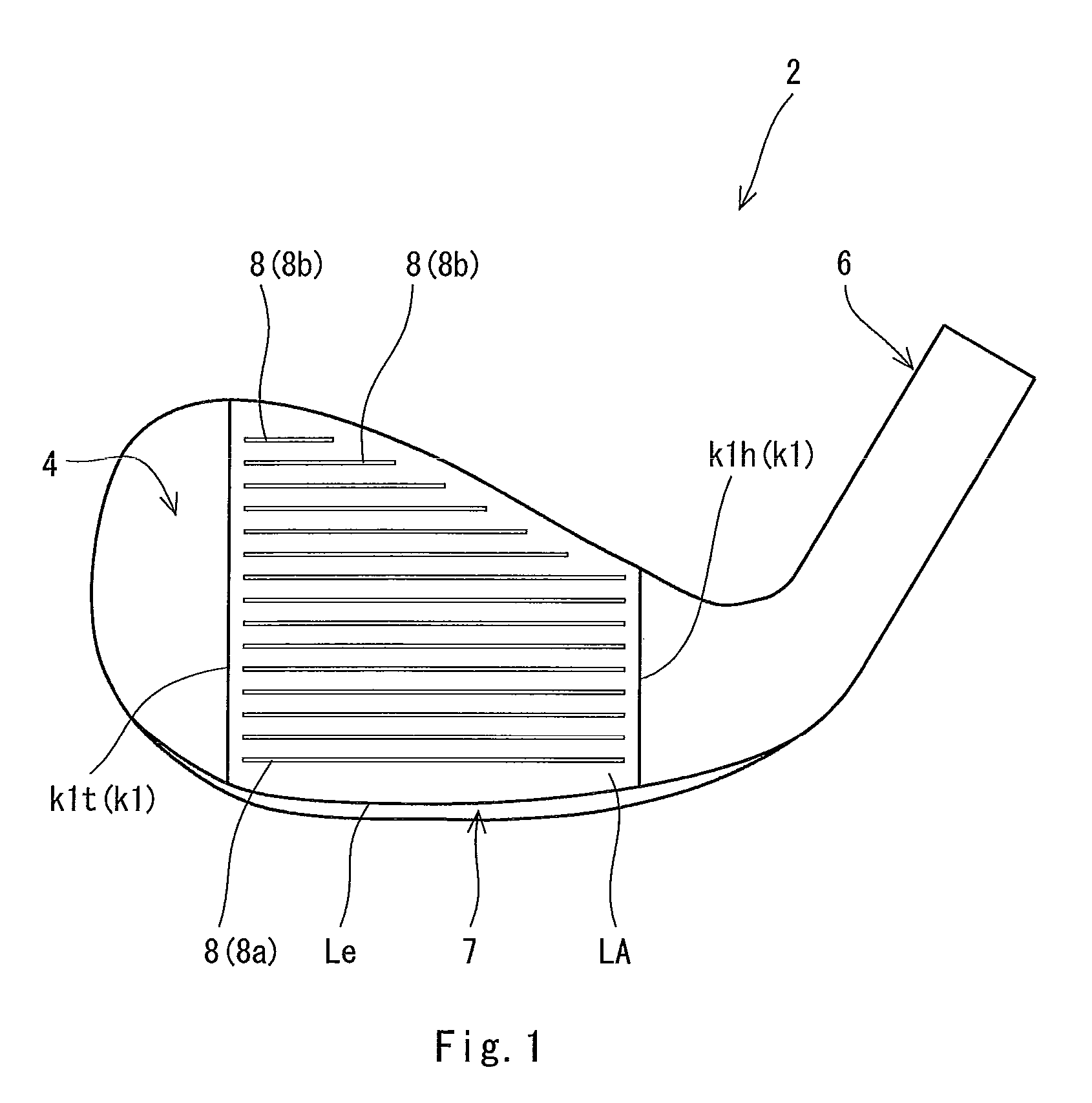
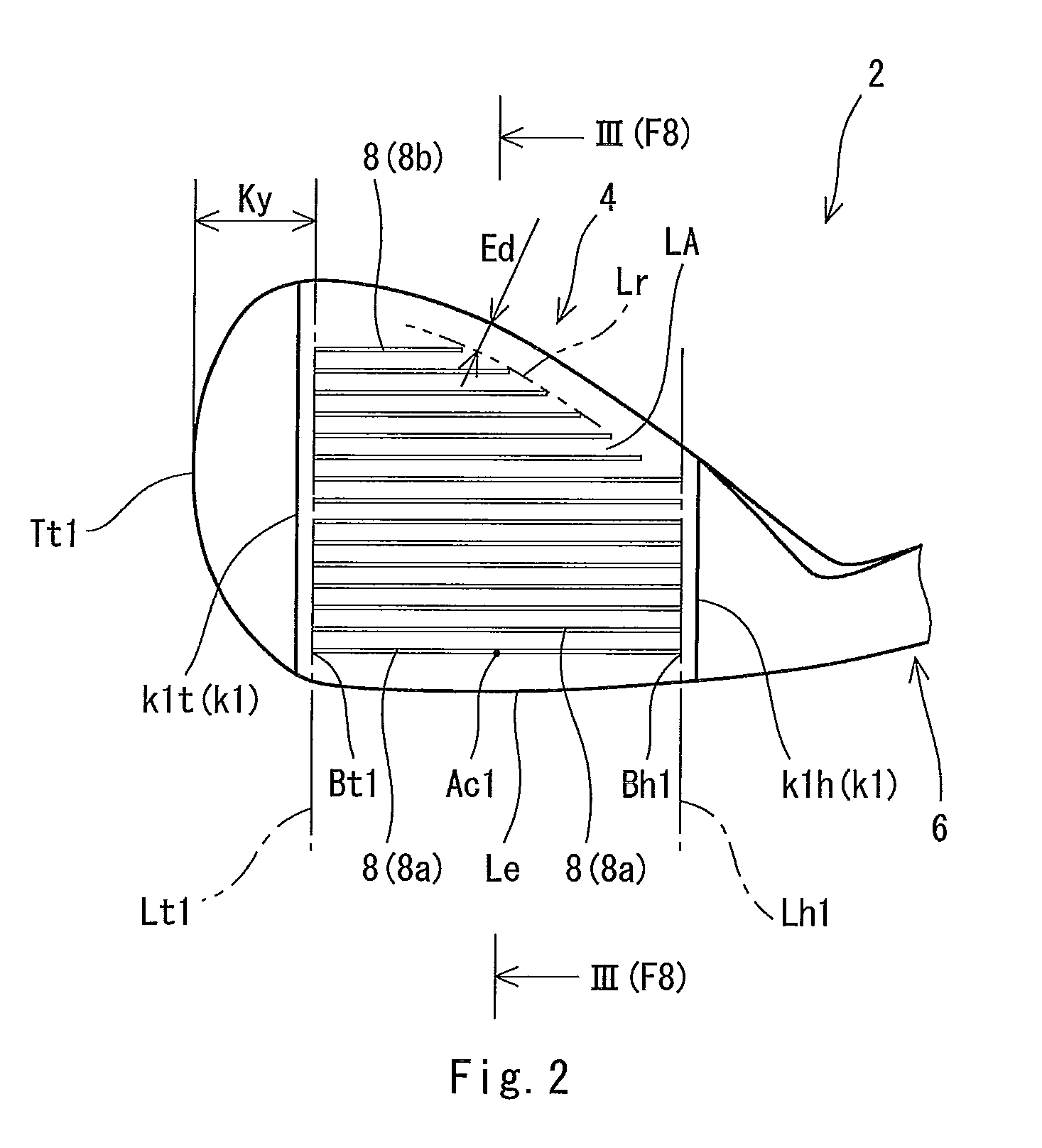
[0172]The face lines were disposed as shown in FIGS. 1 and 2. A distance Ed (see FIG. 2) between the heel side end of the non-longest line and the edge of a face was set to 5 mm. The shortest distance between a heel side end Bh1 (see FIG. 2) of the face line closest to a sole and a leading edge Le was set to 2 mm. The shortest distance between a toe side end Bt1 (see FIG. 2) of the face line closest to the sole and the leading edge Le was set to 2 mm. The shortest distance between a cent...

examples 2 and 3

[0176]Heads of examples 2 and 3 were obtained in the same manner as in the example 1 except that the shape of the cutter and / or the distance T1 (mm) were changed and the shape of the groove was set so as to satisfy values shown in Table 1. Clubs of the examples 2 and 3 were obtained in the same manner as in the example 1 using the heads. These specifications and evaluation results are shown in the following Table 1.


PUM

PropertyMeasurementUnit
depthaaaaaaaaaa
angle θ2aaaaaaaaaa
angle θ2aaaaaaaaaa

Abstract

A head 2 has a face line 8 having a depth of D1 (mm). When a boundary between a land area and a face line is defined as a point Pa; a point of which a depth is [D1 / 4] (mm) is defined as a point Pb; a point of which a depth is [D1 / 2] (mm) is defined as a point Pc; a point of which a depth is [(D1)×(¾)] (mm) is defined as a point Pd; a point of which a depth is 0.002 (mm) is defined as a point Px; a radius of a circle CL1 passing through three points of the point Pa, the point Pb, and the point Pc is defined as R3 (mm); a straight line passing through the point Pa and the point Px is defined as a straight line Lax; and an angle between the land area and the straight line Lax is defined as θ2 (degree), the radius R3 is 0.2 (mm) or greater and 0.4 (mm) or less, and the angle θ2 is 10 degrees or greater and 50 degrees or less.

Description

[0001]This application claims priority on Patent Application No. 2009-128370 filed in JAPAN on May 28, 2009, the entire contents of which are hereby incorporated by reference.BACKGROUND OF THE INVENTION[0002]1. Field of the Invention[0003]The present invention relates to a golf club head having face lines.[0004]2. Description of the Related Art[0005]Face lines are formed on many golf club heads. The face lines can contribute to increase in a backspin rate of a hitting ball. The face lines can suppress fluctuation in the backspin rate.[0006]In golf in case of rain, a face impacts a ball with water present between the face and the ball. The water can reduce friction between the face and the ball. The face lines can suppress the influence of the water. In other words, the face lines can enhance spin performance in a wet condition.[0007]In the case of shot from the rough, the face impacts the ball with grass (lawn grass) present between the face and the ball. The grass can reduce the fr...

Claims


Application Information

Patent Timeline
Patent Type & Authority Patents(United States)
IPC IPC(8): A63B53/04A63B102/32
CPCA63B53/047A63B53/04A63B53/0487A63B2053/0408Y10T409/303752A63B2209/00A63B2209/02A63B53/0466A63B2053/0445A63B53/0445A63B53/0408A63B60/00
Inventor NAKAMURA, TAKASHIYOKOTA, MASATOSHI
Owner SUMITOMO RUBBER IND LTD
Why Eureka
Try Eureka