Method of estimating the dust load of an ESP, and a method and a device of controlling the rapping of an ESP
a technology of dust load and esp, which is applied in the direction of electric supply techniques, separation processes, instruments, etc., can solve the problems of increasing the investment and operating cost of esp, and achieve the effects of improving the dust removal efficiency of existing esp, increasing the removal capability of collecting electrode plates, and increasing the removal capability
- Summary
- Abstract
- Description
- Claims
- Application Information
AI Technical Summary
Benefits of technology
Problems solved by technology
Method used
Image
Examples
third embodiment
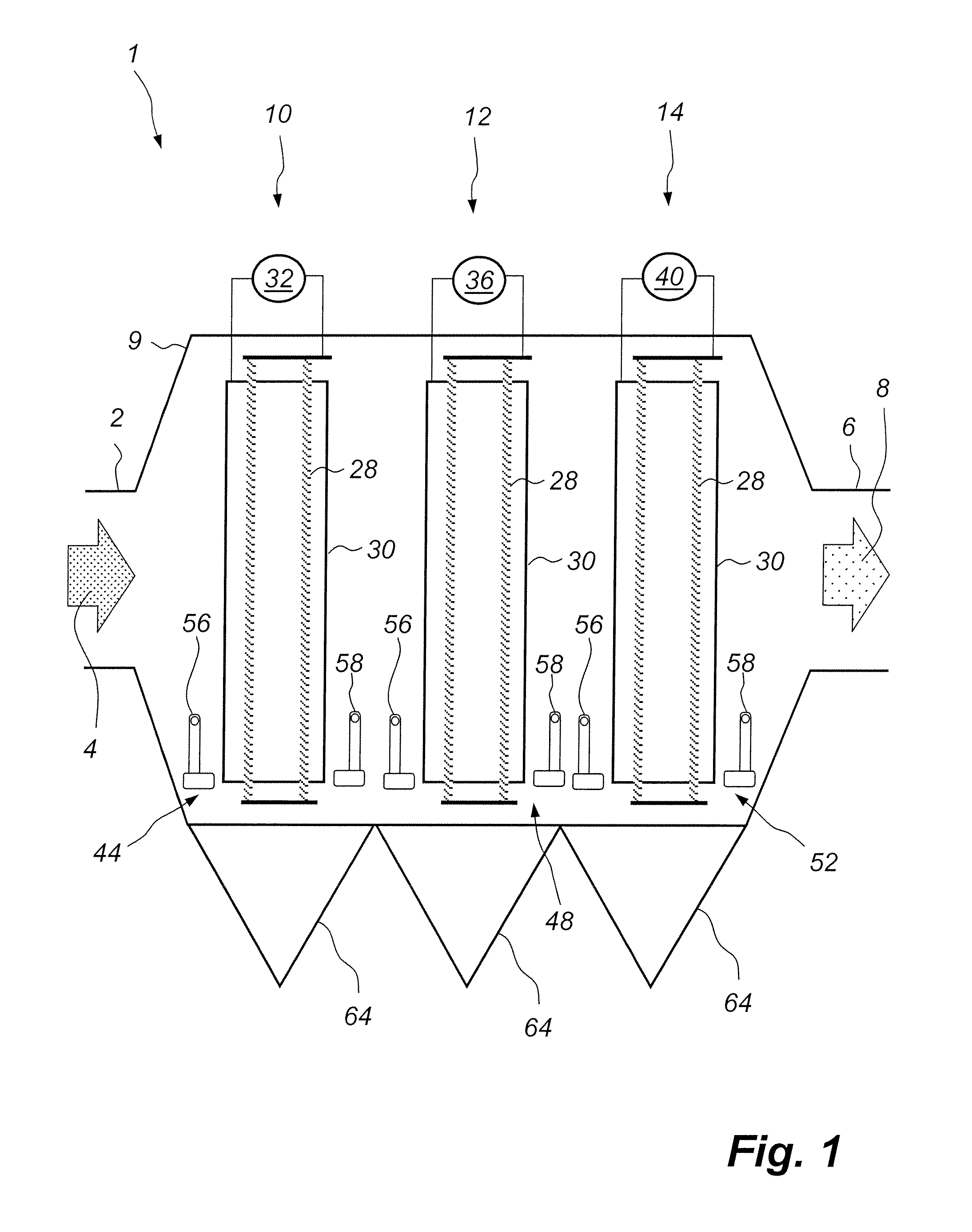
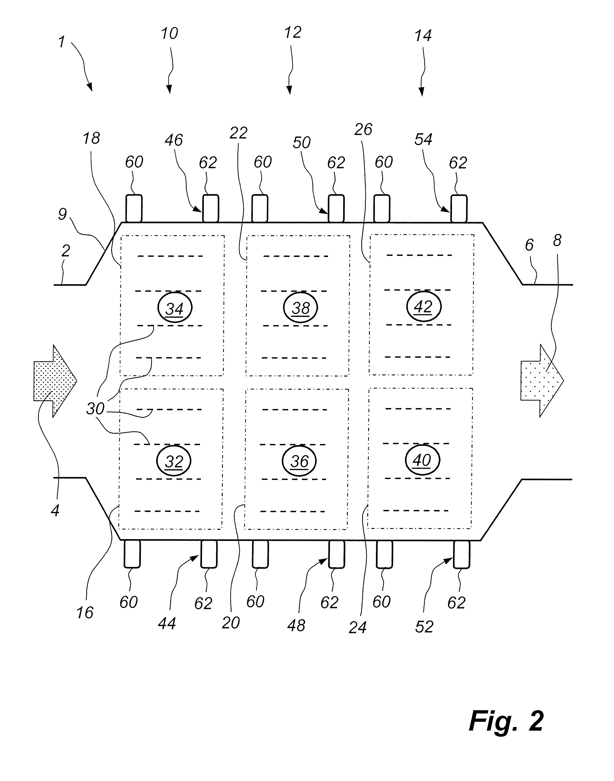
[0078]While it has been described hereinbefore, with reference to FIG. 10, that the downstream second bus-section 20 is rapped prior to each rapping of the upstream first bus-section 16, it is also possible to control the rapping of the downstream second bus-section 20 in alternative manners. According to one alternative manner a rapping event of the downstream second bus-section 20 is initiated only prior to every second occasion of initiating a rapping event in the upstream first bus-section 16, such that two consecutive rapping events of the upstream first bus-section 16 will correspond to one rapping event of the downstream second bus-section 20. Obviously, in some cases it may even be sufficient to initiate a rapping event of the downstream second bus-section 20 prior to every third, or every fourth or more, occasion of initiating a rapping event in the upstream first bus-section 16, when operating in accordance with this third embodiment of the second aspect of the present inv...
fourth embodiment
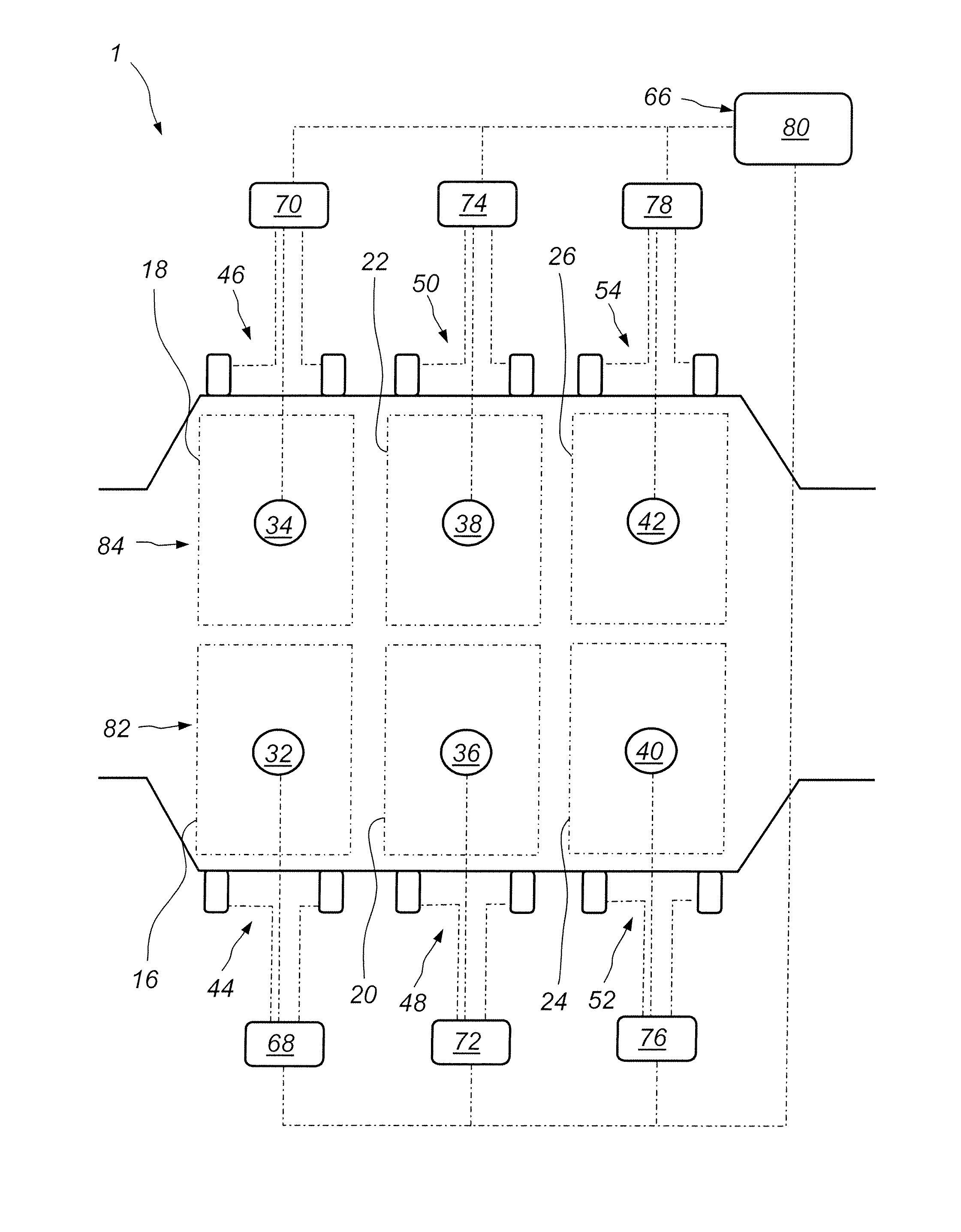
[0080]FIG. 11 illustrates the second aspect of the present invention. FIG. 11 illustrates, schematically, an electrostatic precipitator, ESP, 101 having four bus-sections 116, 118, 120 and 122 placed in series. The flue gas 104 enters the first bus-section 116, then continues further to the second bus-section 118, to the third bus-section 120, and, finally, to the fourth bus-section 122. The cleaned flue gas 108 leaves the fourth bus-section 122. The first bus-section 116 and the second bus-section 118 form a first pair 124 of bus-sections in which the first bus-section 116 will operate as the main collecting unit, and the second bus-section 118 will operate as a guard bus-section collecting dust particles that have not been removed by the first bus-section 116. The first bus-section 116 and the second bus-section 118 of the first pair 124 of bus-sections may thus be operating in the manner that has been described hereinbefore with reference to FIG. 10, i.e., a process computer, not...
second embodiment
[0084]the second aspect of the present invention, which has been described hereinbefore with reference to FIG. 9, shows the following chain of procedural checks: in order to allow rapping in a first bus-section a check is first made in accordance with step 92 of FIG. 7, to determine if rapping is needed in the second bus-section. If rapping is required in the second bus-section then a check is made in accordance with step 100 of FIG. 9, to determine whether rapping is required in the third bus-section. Thus, all three bus-sections are linked together in such a way that a first check is made from the standpoint of the first bus-section with regard to the second bus-section, and a second check is then made from the standpoint of the second bus-section with regard to the third bus-section. An alternative to this way of linking the three consecutive bus-sections together is to make one combined check made from the standpoint of the first bus-section with regard to both the second and th...
PUM
| Property | Measurement | Unit |
|---|---|---|
| voltage | aaaaa | aaaaa |
| time | aaaaa | aaaaa |
| waiting time | aaaaa | aaaaa |
Abstract
Description
Claims
Application Information
 - R&D
- Intellectual Property
- Life Sciences
- Materials
- Tech Scout
- Unparalleled Data Quality
- Higher Quality Content
- 60% Fewer Hallucinations
Browse by: Latest US Patents, China's latest patents, Technical Efficacy Thesaurus, Application Domain, Technology Topic, Popular Technical Reports.
© 2025 PatSnap. All rights reserved.Legal|Privacy policy|Modern Slavery Act Transparency Statement|Sitemap|About US| Contact US: help@patsnap.com


