Hearing instrument with improved venting and miniature loudspeaker therefore

a technology of acoustical venting and hearing aids, which is applied in the direction of hearing aid mounting/interconnection, hearing aid venting, electric devices, etc., can solve the problems of occupying the shell or earmold surface of the hearing aid, and the tip portion of the earmold is particularly problematic, so as to facilitate coupling, relax the positioning of individual elements, and reduce the space requirements

Active Publication Date: 2012-12-11
SONION NEDERLAND
View PDF14 Cites 75 Cited by
  • Summary
  • Abstract
  • Description
  • Claims
  • Application Information

AI Technical Summary

Benefits of technology

[0016]The first and second sound ports are preferably arranged in substantially opposing wall portions of the speaker housing. The speaker housing may have a substantially rectangular or cylindrical shape with a central longitudinal plane. These shapes are often advantageous in allowing the speaker housing to be installed in the tip portion of the hearing aid earmold in a space-efficient manner. The first and second sound ports may be arranged in the central longitudinal plane since this arrangement facilitates coupling of the first sound port to a distant shell sound port of an associated hearing aid earmold.
[0017]Naturally, the microphone may be positioned so as to detect sound entering the second sound opening or may be positioned at another position in or at the opposed surface. As this surface is adapted to point away from the ear canal of the person, space requirements may be more relaxed and there may be room for both the second sound opening and an opening to a microphone.
[0018]Typically, the first surface is adapted to be positioned in the ear canal, either deeply therein or at the entrance thereof. The opposed surface, however, may be positioned within the ear canal or in the outer ear of the person. Thus, this surface may be much larger, facilitating a much more relaxed positioning of the individual elements.
[0020]By allowing sound from the second sound opening to exit the first sound opening, the so-called occlusion effect may be avoided or reduced. Due to e.g. space requirements, this sound is output via the same opening delivering the sound from the loudspeaker.
[0026]The symmetrical construction of the miniature speaker is preferably implemented so that a moving mass of the first motor assembly and displaceable diaphragm is substantially equal to a moving mass of the second motor assembly and displaceable diaphragm. This fully symmetrical construction can provide a high degree of cancellation of mechanical vibration of the miniature loudspeaker during actuation. The cancellation of mechanical vibration makes it possible to attach or mount the miniature speaker directly (i.e. without a resilient suspension) to the earmold shell for a wide range of hearing aid applications. For other hearing aid applications, the mechanical vibration cancellation will at least relax vibration isolation requirements for any speaker suspension member. This is especially so when the signals fed to the first and second motor assemblies are the same.
[0035]In one embodiment of the invention, the earmold shell and the miniature loudspeaker comprise mating first and second electrically conducting contact pairs adapted to provide solderless / solderfree electrical interconnection between the miniature loudspeaker and electronic assembly of the hearing aid. One pair of the first and second electrically conducting contact pairs may, for example, comprise an electrically conducting spring such as a helical, torsion, or leaf spring. This embodiment is particularly advantageous in combination with the above-mentioned fully symmetrical dual-diaphragm miniature loudspeaker because of a significantly reduced level of mechanical vibration of the loudspeaker compared to single diaphragm miniature speakers.

Problems solved by technology

A significant drawback of prior art vented hearing aid earmolds has been the occupation of shell or earmold surface area near the tip portion of the shell by two separate sound ports.
The tip portion of the earmold is particularly problematic in this context because of severe size constraints dictated by the requirement of fitting deeply into a user's ear canal at a position proximate to the eardrum.

Method used


Image

  • Hearing instrument with improved venting and miniature loudspeaker therefore
  • Hearing instrument with improved venting and miniature loudspeaker therefore
  • Hearing instrument with improved venting and miniature loudspeaker therefore

Examples


Embodiment Construction

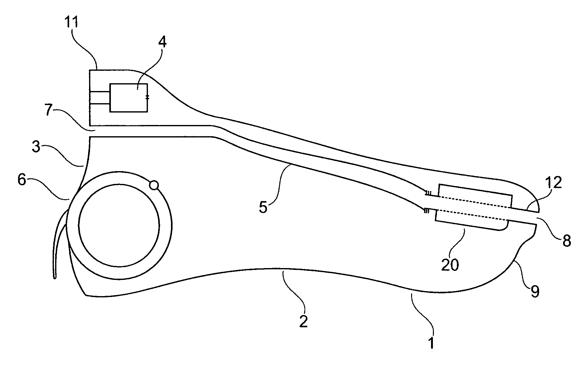
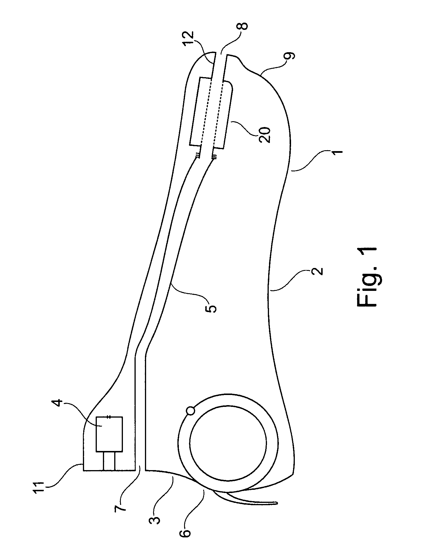
[0044]FIG. 1 is a schematic illustration of an ITC hearing aid earmold 1. The earmold 1 encloses various electronic, mechanical and electroacoustic components and functions to shield these from an external environment.

[0045]The earmold 1 comprises an at least partly hollow shell 2 having an outer contour shaped to fit a hearing aid user's ear canal. In the present embodiment of the invention, the earmold 1 includes a customized shell 2 that has been from an ear canal impression of the hearing aid user's ear canal. The ear canal impression may be provided in either virtual form, such as a digital computer representation, or in tangible form such as a physical impression. In other embodiments of invention, the shell 2 is supplied with a prefabricated outer contour, preferably including elastomeric or deformable shell portions that can fit into a plurality of ear canal shapes and sizes.

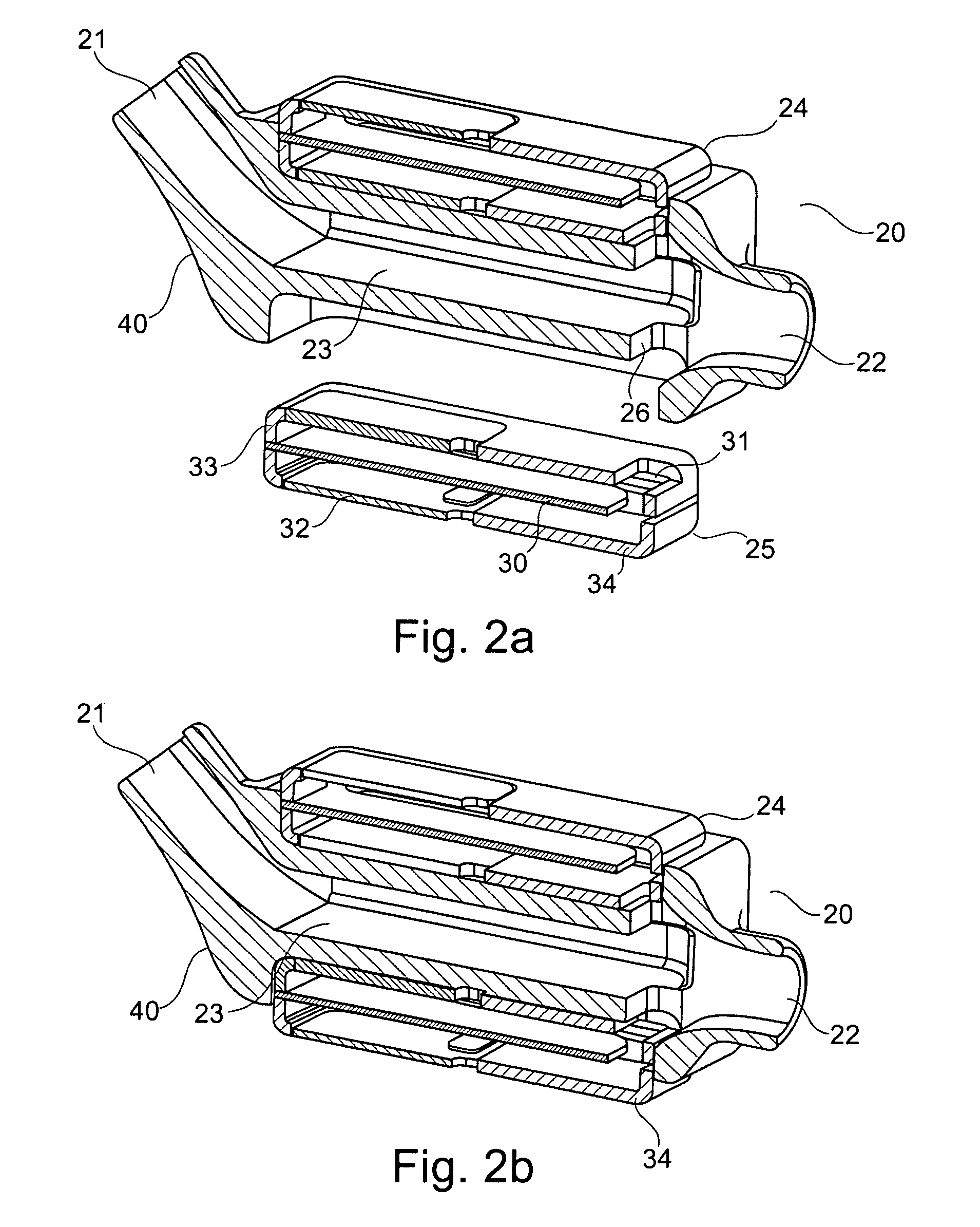
[0046]The earmold 1 comprises a miniature dual-diaphragm speaker 20 with a through-going canal or ven...


PUM


Abstract

The present invention relates to improvements in acoustical venting of hearing aid earmolds and to miniature loudspeakers with housing structures configured to support improved hearing aid venting. The miniature loudspeaker comprises a front chamber with first and second separate sound ports so as to allow the front chamber to form an integral part of the acoustical vent of the hearing aid earmold. Thus, while using the same opening in the hearing aid for both sound output and venting, sound from the outside of the hearing aid may be introduced into the users ear via the same opening.

Description

RELATED APPLICATION DATA[0001]This application is a nonprovisional application of U.S. Provisional Application No. 61 / 131,659, filed Jun. 11, 2008, which is incorporated herein by reference.FIELD OF INVENTION[0002]The present invention relates to improvements in acoustical venting of hearing aid earmolds and to miniature loudspeakers with housing structures configured to support improved hearing aid venting.BACKGROUND OF THE INVENTION[0003]It is well-known in the art to include an acoustical vent in an earmold of a hearing aid or instrument. The acoustical vent is a sound duct or channel extending from a sound port in a tip portion of a hearing aid earmold to another sound port positioned in an end surface of the earmold so as to allow sound propagation between the otherwise occluded ear canal (when the hearing aid is mounted firmly in the ear) and the surroundings. A discussion of function, advantages and drawbacks of acoustical venting in hearing instruments can for example be fou...

Claims


Application Information

Patent Timeline
Patent Type & Authority Patents(United States)
IPC IPC(8): H04R25/00
CPCH04R25/60H04R25/604H04R2460/11B33Y80/00H04R25/609
Inventor VAN HALTEREN, AART ZEGER
Owner SONION NEDERLAND
Why Eureka
Try Eureka