Cavitation erosion reduction strategy for valve member and fuel injector utilizing same

a fuel injector and valve member technology, applied in the direction of fuel injectors, valve housings, machines/engines, etc., can solve the problems of affecting the operation, the cavitation erosion is also undesirable, and the fuel injector is prone to failure. , to achieve the effect of reducing cavitation erosion

Active Publication Date: 2012-12-18
CATERPILLAR INC
View PDF15 Cites 7 Cited by
  • Summary
  • Abstract
  • Description
  • Claims
  • Application Information

AI Technical Summary

Problems solved by technology

Furthermore, cavitation damage can in some cases potentially lead to premature fuel injector failure rather than simple wear and tear on the various inner surfaces defining the fuel passageways through the fuel injector.
The collapse of cavitation bubbles may eventually erode an annular surface on the valve member and may affect its operation, the operation of the fuel injector, and the operation of the engine.
Cavitation erosion is also undesirable because it produces small metallic particles that can cause scuffing and seizure in moving parts of a fuel system.
Unfortunately, modeling fluid systems to predict the occurrence of cavitation, as well as potential magnitudes of damage and their respective locations due to cavitation has proven to be extremely difficult.
Thus, a computer aided design strategy for avoiding some cavitation damage problems is not realistic as the modeling tools available to simulate various different design shapes and evaluate the same for potential cavitation damage are not capable of accurately and reliably predicting some cavitation damage problems.

Method used


Image

  • Cavitation erosion reduction strategy for valve member and fuel injector utilizing same
  • Cavitation erosion reduction strategy for valve member and fuel injector utilizing same
  • Cavitation erosion reduction strategy for valve member and fuel injector utilizing same

Examples


first embodiment

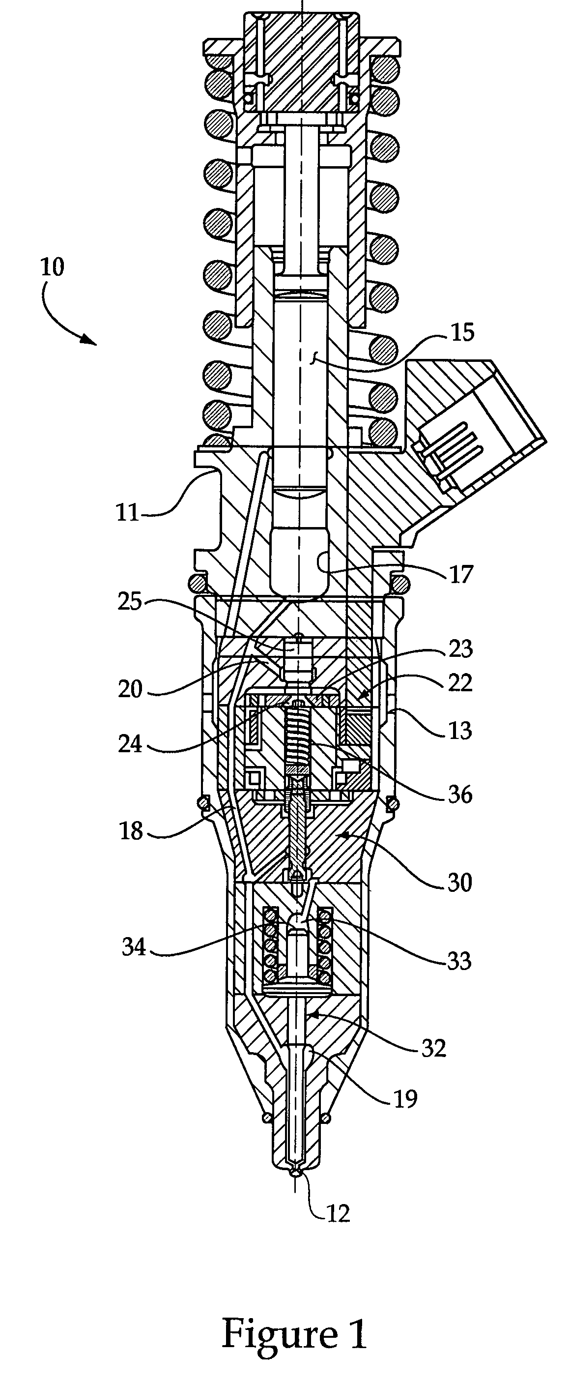
[0018]Referring now to FIGS. 4 and 6, a valve member 125 includes a single large annulus 126 that is defined in part by annular valve surface 143. Although this design performs well with regard to cavitation, there is always room for improvement. After many hours of operation involving many injection cycles, it is possible that cavitation that may occur around valve member 125 may begin to erode annulus 126 at location 110 (which is on the low pressure side of the circuit) according to pattern 111. The cavitation bubbles that occur around valve member 125 are believed to develop shortly after the closing of annular valve seat 29. When this occurs, the momentum of the fluid spilling through spill passage 20 is believed to have a water hammer effect, in that a vacuum develops adjacent to valve seat 29, and flow conditions cause at least some of the cavitation bubbles to collapse adjacent to the valve member 125 at location 110. Over time, it is possible that the continuous collapsing...

second embodiment

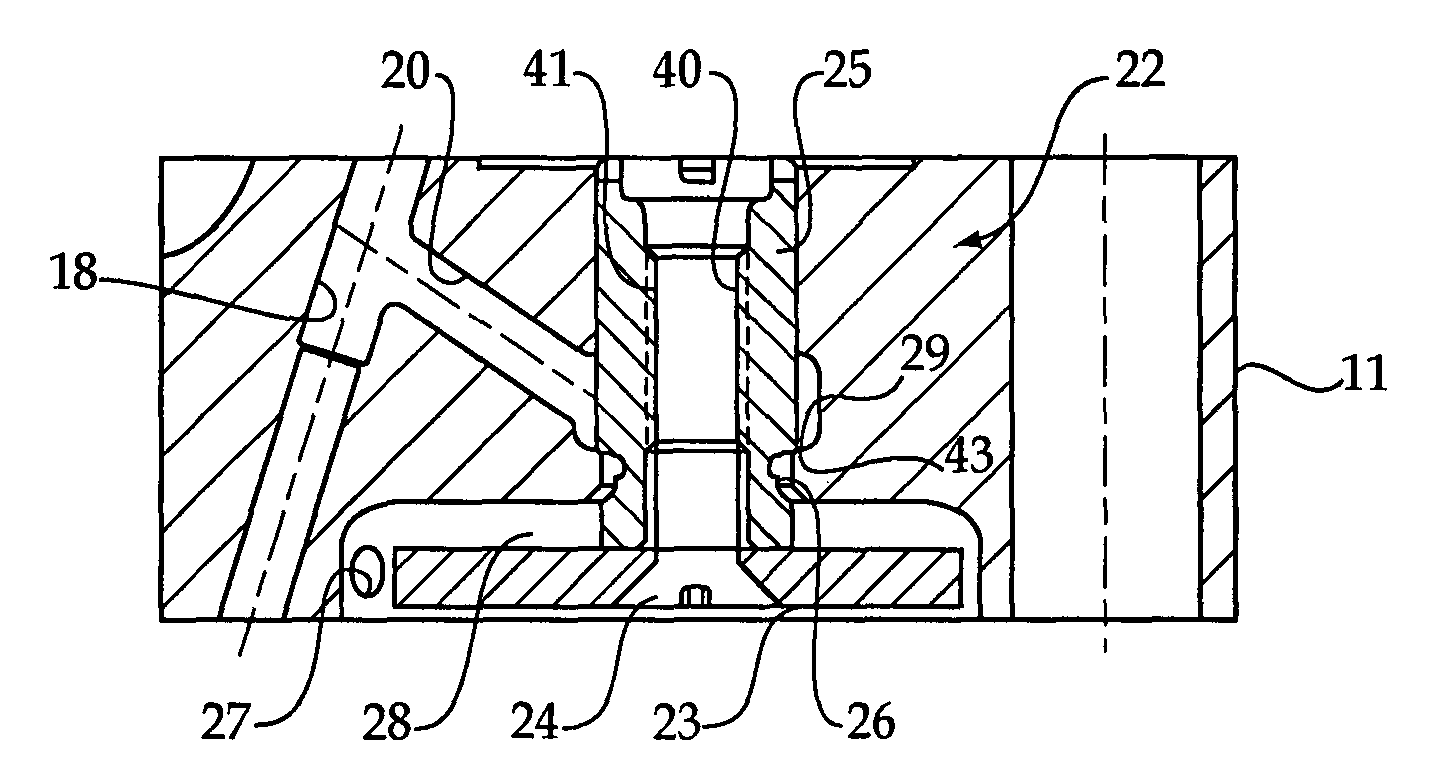
[0019]In order to both minimize the amount of debris set loose in the fuel system due to cavitation erosion and to minimize the likelihood of cavitation erosion in the first place, the present disclosure contemplates a rather counterintuitive solution. In particular, the present disclosure teaches that by adding an annulus, such as annulus 45 in the vicinity of, and with a magnitude (shape and volume) associated with the potential cavitation erosion pattern 111 illustrated in FIG. 6, cavitation erosion may be reduced, and potentially actually avoided. In other words, it is believed that by preemptively removing material that might otherwise be eventually eroded via cavitation, flow patterns around the valve member may change such that either the cavitation bubbles no longer are generated, or that they collapse at a location away from the valve member to minimize the likelihood of erosion in the relevant locations or cause any erosion that may occur to occur on a less critical surfac...


PUM


Abstract

A mechanically actuated electronically controlled unit injector includes an electronically controlled spill valve to precisely control timing of fuel pressurization within a fuel pressurization chamber. Cavitation bubbles may be generated in the region of the valve seat when the spill valve member is closed to raise fuel pressure in the fuel injector. This cavitation can cause erosion on the spill valve member and the surrounding injector body. In order to preempt cavitation damage, the valve member may be modified to include a compound annulus that includes a small annulus that corresponds to an identified cavitation damage pattern. Although the generation of cavitation bubbles may continue after such a strategy, cavitation erosion, and the associated liberation of metallic particles into the fuel system can be reduced, and maybe eliminated, by the preemptive cavitation reduction strategy.

Description

TECHNICAL FIELD[0001]The present disclosure relates generally to a cavitation erosion reduction strategy in a fuel injector, and more particularly to a valve member of a fuel injector incorporating the cavitation erosion reduction strategy.BACKGROUND[0002]Most fuel injectors include one or more electronically controlled valves that open and close various fuel passageways to facilitate control over fuel injection events. One class of such fuel injectors is typically identified as a mechanically actuated, electronically controlled unit injector (MEUI) which utilize an electronically controlled valve to precisely control a timing at which fuel in the fuel injector becomes pressurized. In particular, a rotating cam periodically advances a plunger to pressurize fuel in a fuel pressurization chamber, but pressure does not rise until a spill valve is closed. If a spill valve is closed during a plunger stroke, fuel pressure quickly rises followed by opening of a nozzle outlet to perform an ...

Claims


Application Information

Patent Timeline
Patent Type & Authority Patents(United States)
IPC IPC(8): B05B1/30
CPCF02M57/023F02M59/366F02M61/168F02M63/0015F02M63/0031F02M65/00F02M2200/04F02M2200/80F02M2200/8076
Inventor LEWIS, STEPHEN R.COLDREN, DANA R.MUELLER, JEFFREY J.YACOUB, VICTOR
Owner CATERPILLAR INC
Why Eureka
Try Eureka