Servo control synchronous advancing device for unit pump or unit oil sprayer

A servo and advancer technology, applied in fuel injection control, engine control, fuel injection pump, etc., can solve the problem of high fuel injection volume and achieve the effect of precise control

Inactive Publication Date: 2002-06-12
斯塔纳迪恩公司
View PDF1 Cites 1 Cited by
  • Summary
  • Abstract
  • Description
  • Claims
  • Application Information

AI Technical Summary

Problems solved by technology

Although the engine has low emissions during steady state operation (such as when cruising), the fuel injection vo

Method used


Image

  • Servo control synchronous advancing device for unit pump or unit oil sprayer
  • Servo control synchronous advancing device for unit pump or unit oil sprayer
  • Servo control synchronous advancing device for unit pump or unit oil sprayer

Examples


Embodiment Construction

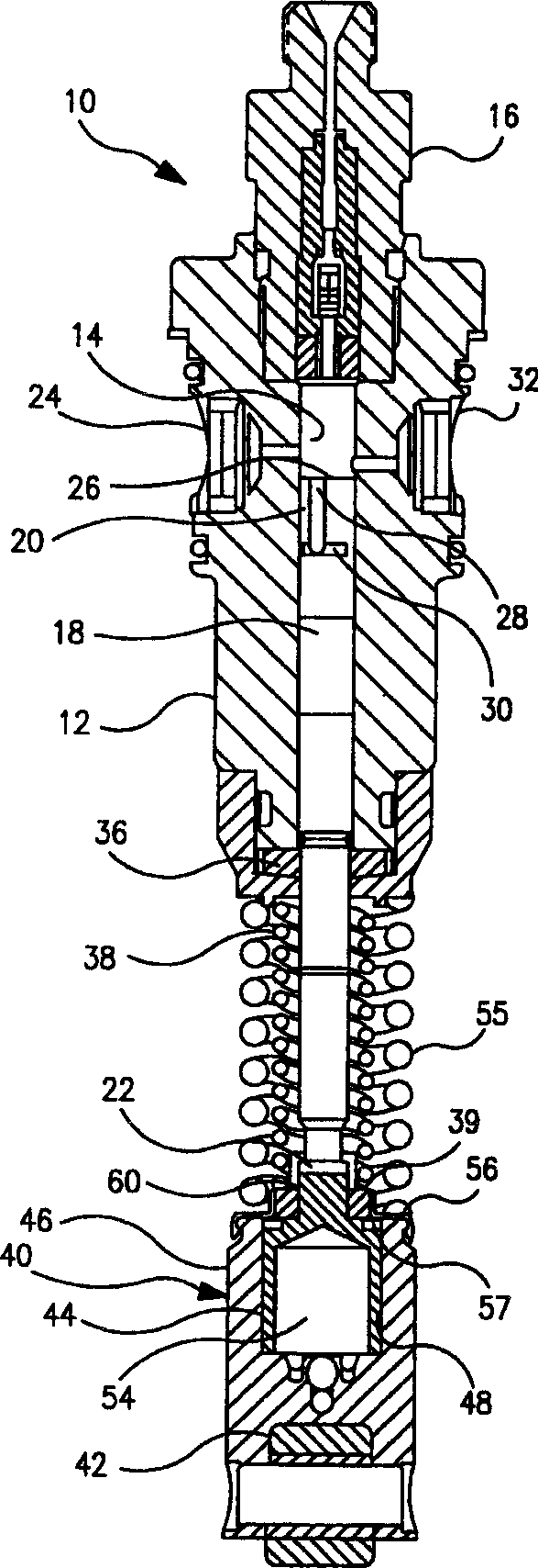
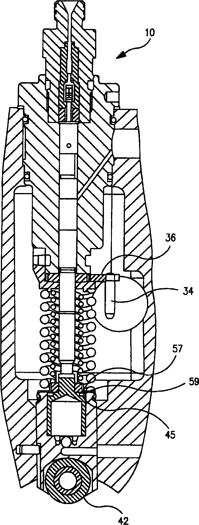
[0028] Figure 1A with 1BIllustrated is a fuel injection unit pump 10 or unit injector that can be modified by the present invention. Isocratic pump 10 includes a body 12 defining a longitudinal suction chamber 14, with a head 16 mounted at one end of the body coaxially with the suction chamber. A generally cylindrical suction plunger 18 is disposed within the suction chamber 14 for reciprocating movement therein. The suction plunger 18 has a suction end 20 disposed towards the head 16 and a counter-drive end 22 projecting from the unit pump body 12 . An infusion / overflow opening 24 is provided in the body 12, and movement of the leading edge 26 of the plunger suction end 20 past the infusion / overflow opening determines the start of the infusion process. The upper and lower channel portions 28 , 30 partially surround the outer diameter of the suction plunger 18 . The alignment of the lower passage portion 30 with the fill / overflow port 24 is used to determine the end of the...


PUM


Abstract

A hydraulically actuated servo piston and hydraulic advance piston are integrated into the cam follower of a unit pump or injector to provide variable advance for an injection event produced by the pump or injector. The servo piston is nested in the advance piston with fluid passageways in the advance piston selectively opened or closed by movement of the servo piston. The full pressure of a hydraulic pump is available to the advance piston for powering the advance function, while stepwise reduced levels of hydraulic pressure from the same hydraulic pump are applied to control movement of the servo piston. A damping orifice restricts flow of hydraulic fluid to and from the servo piston.

Description

technical field [0001] The present invention relates to a timing advance for use in fuel injection systems of the type commonly used in vehicle engines. Specifically, the present invention is an improvement over hydraulically actuated synchro advancer technology described in U.S. Patent Application Serial No. 09 / 638,758, "Synch Advancer for Unit Pump or Unit Injector" filed August 14, 2000 "Timing Advance Piston for Unit Pump or Unit Injector and Method Therefor," the disclosure of which is incorporated herein by reference. Background technique [0002] The automotive industry is under constant pressure to reduce unnecessary fuel injection from the internal combustion engines that power nearly all vehicles currently in use throughout the world. Although the engine has low emissions during steady state operation (such as while cruising), the fuel injection quantity is still high during non-steady state processes of the engine, such as start-up, accele...

Claims


Application Information

Patent Timeline
IPC IPC(8): F02M59/10F02M59/30F02M63/00
CPCF02M59/102F02M2200/304F02M59/30
Inventor 马克·杜凯特肯尼思·H·克罗普弗
Owner 斯塔纳迪恩公司
Why Eureka
Try Eureka