Opposed hydraulic free piston engine with hydraulic synchronizing mechanism and driving method of opposed hydraulic free piston engine.

A piston engine, hydraulic synchronization technology, used in free piston engines, machines/engines, liquid fuel engines, etc., can solve problems such as reducing power density, increasing system volume and complexity, and increasing costs

Active Publication Date: 2020-12-04
TIANJIN UNIV
View PDF9 Cites 1 Cited by
  • Summary
  • Abstract
  • Description
  • Claims
  • Application Information

AI Technical Summary

Problems solved by technology

[0003] At present, the research on the opposed hydraulic free-piston engine is still in the exploratory stage. One of the key issues is the synchronization method of the pistons on both sides. To make the two opposed pistons fully synchronized usually requires precise control valves or complex mechanisms. Commonly used in the market The precise contr

Method used


Image

  • Opposed hydraulic free piston engine with hydraulic synchronizing mechanism and driving method of opposed hydraulic free piston engine.

Examples


Embodiment 1

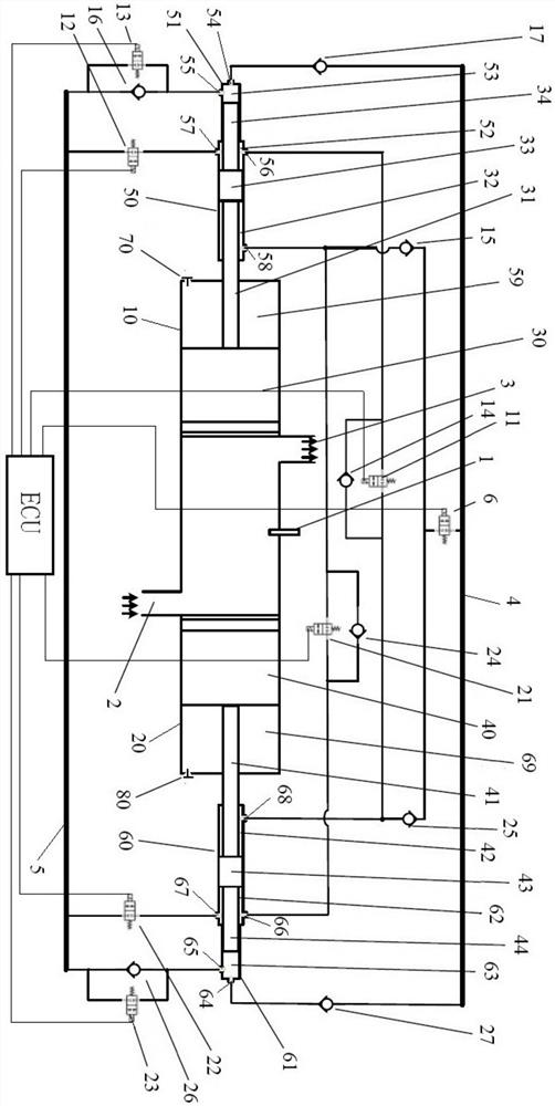
[0070] An opposed free-piston engine with a hydraulic synchronization mechanism, comprising: a high-pressure working fluid circuit 4, a low-pressure working fluid fluid circuit 5, an electronic control unit ECU, an injector 1, an air inlet 2, and an exhaust port 3, a total of The first cylinder liner 10 and the second cylinder liner 20 are axially and symmetrically distributed, the first piston 30 matched with the first cylinder liner, the first piston rod 31 connected with the first piston, and the other end of the first piston rod. The first piston rod sleeve 51, the first high pressure working medium output chamber 53 formed by the first piston rod sleeve and the end face of the first piston rod, the second piston 40 matched with the second cylinder sleeve, the second piston 40 connected with the second piston. Two piston rods 41, a second piston rod sleeve 61 connected to the other end of the second piston rod, a second high pressure working medium output cavity 63 formed b...

Embodiment 2

[0091] The structure of the opposed free-piston engine is exactly the same as that of Embodiment 1, and a method for driving an opposed free-piston engine with a hydraulic synchronizing mechanism implemented on the above-mentioned engine is as follows:

[0092] Close the exhaust port, the intake port is completed and closed, and all solenoid valves are closed by default;

[0093] Step 0: Adjust the piston to the bottom dead center, the specific process is as follows: open the first air valve, the second air valve, the first solenoid valve, the second solenoid valve, the third solenoid valve, the fourth solenoid valve, and the fifth solenoid valve , the sixth solenoid valve and the seventh solenoid valve; part of the liquid working medium in the output chamber of the first high pressure working medium is pumped to the low pressure working medium liquid circuit by the fifth solenoid valve, and part of the liquid working medium in the third synchronizing cavity is pumped by the th...

Embodiment 3

[0101] The structure of the opposed free-piston engine is exactly the same as that of Embodiment 1. Steps 1, 2, 3, and 4 are the same as those of Embodiment 1. The difference lies in Step 3-1, specifically:

[0102] Step 3-1: Taking the position of the first piston as a reference, if the phase of the second piston lags behind, pressurize the second air tank with the intake air through the second valve; if the phase of the second piston is ahead, pass the second The air valve is deflated to depressurize the second air tank, and the amount of deflation or intake is subject to eliminating the phase deviation.


PUM


Abstract

The invention relates to an opposed hydraulic free piston engine with a hydraulic synchronizing mechanism and a driving method of the opposed hydraulic free piston engine. The opposed free piston engine comprises a high-pressure working medium liquid path, a low-pressure working medium liquid path, an electronic control unit, an oil sprayer, a gas inlet, an exhaust opening, a first cylinder sleeve, a second cylinder sleeve, a first piston matched with the first cylinder sleeve, a first piston rod connected with the first piston, a first high-pressure working medium output cavity connected withthe other end of the first piston rod, a second piston matched with the second cylinder sleeve, a second piston rod connected with the second piston, a second high-pressure working medium output cavity connected with the other end of the second piston rod, a high-pressure working medium liquid path, and the hydraulic synchronizing mechanism, wherein the first cylinder sleeve and the a second cylinder sleeve are coaxial and symmetrically distributed According to the opposed hydraulic free piston engine with the hydraulic synchronizing mechanism and the driving method of the opposed hydraulic free piston engine, a first synchronizing cavity and a fourth synchronizing cavity of the hydraulic synchronizing mechanism communicate, and a second synchronizing cavity and a third synchronizing cavity communicate, so that two synchronizing loops are formed; and due to the property that a liquid working medium is difficult to compress, mutual containing and mutual restraining are achieved, and the pistons on the two sides can synchronously move.

Description

Technical field: [0001] The invention relates to an opposed hydraulic free piston engine, and further relates to an opposed hydraulic free piston engine with a hydraulic synchronization mechanism and a driving method thereof. Background technique: [0002] With the problem of energy shortage in the world and the crisis of the global environment, people have higher and higher requirements on the power and economy of power plants. Hydraulic free-piston engine is a new type of power unit. It converts heat energy into hydraulic energy through piston and hydraulic pump. It has the characteristics of simple structure, short transmission chain, flexible and variable compression ratio, and is easy to adapt to various fuels. According to its structural form, it can be divided into single-piston, double-piston and opposed-piston type. The opposed-piston type has no cylinder head, which can effectively reduce heat transfer loss, and its symmetrical structure can avoid vibration and inc...

Claims


Application Information

Patent Timeline
IPC IPC(8): F02B71/04F02B75/28F02B33/04F02F1/18F02F1/22F04B17/05F04B1/02F04B53/14F04B53/16F04B53/10
CPCF02B71/04F02B75/285F02B75/282F02B33/04F02F1/186F02F1/22F04B17/05F04B1/02F04B53/14F04B53/162F04B53/10
Inventor 汪洋董翔宇耿鹤鸣李常铭朱瑞王明博胥奇田智
Owner TIANJIN UNIV
Why Eureka
Try Eureka