
Nozzle with exposed vent passage

a vent passage and nozzle technology, applied in plasma welding apparatus, manufacturing tools, welding apparatus, etc., can solve the problems of poor electrode life and limit the available space for swirl rings, and achieve the effects of enhancing nozzle life, limiting available space, and poor electrode li

Active Publication Date: 2012-12-25
HYPERTHERM INC
View PDF26 Cites 59 Cited by
  • Summary
  • Abstract
  • Description
  • Claims
  • Application Information

AI Technical Summary

Benefits of technology

The invention is about a new nozzle design for a plasma torch that improves the performance of the torch by using a vented nozzle and a swirl ring. The new nozzle design allows for a closer injection point of the swirl ring, which results in better electrode life and better swirl control. The swirl ring can be designed to mate with the vented nozzle, and the nozzle can have a plasma gas vent passage formed in it. The invention also includes a new plasma gas vent channel and a cavity in the nozzle for better gas flow control. Overall, the invention enhances the performance and durability of plasma torches by improving the nozzle design and the use of a vented nozzle and swirl ring.

Problems solved by technology

Utilizing a prior art vented nozzle (e.g., such as the nozzle in U.S. Pat. No. 5,317,126) can limit the available space for a swirl ring due to the liner of the nozzle.
While the prior art vented nozzle enhances nozzle life, the prior art vented nozzle causes the swirl ring injection point to be disposed far from the electrode face (e.g., a long distance between the swirl ring injection point and the electrode face), resulting in a poor electrode life.

Method used


Image

  • Nozzle with exposed vent passage
  • Nozzle with exposed vent passage
  • Nozzle with exposed vent passage

Examples


Embodiment Construction

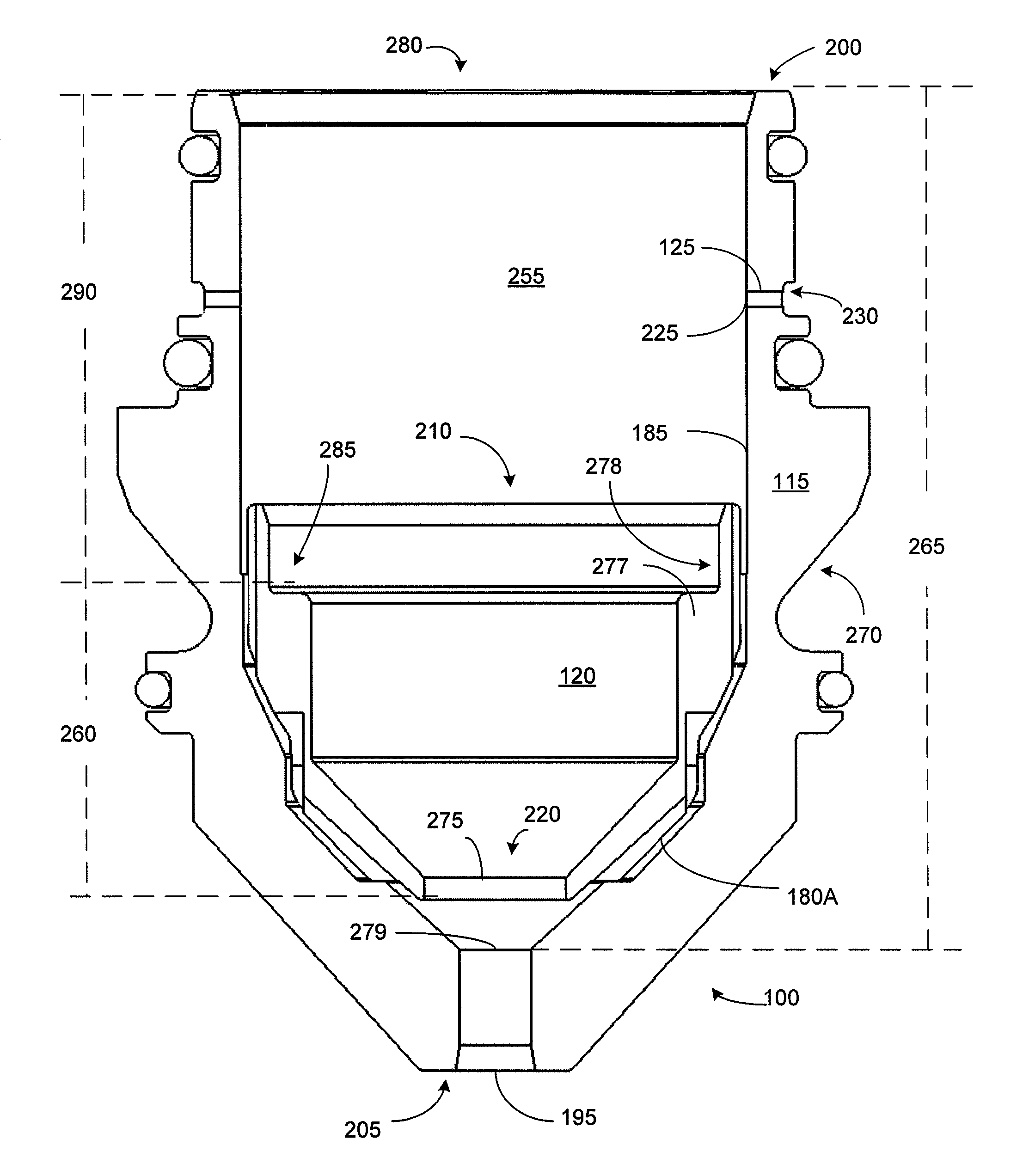
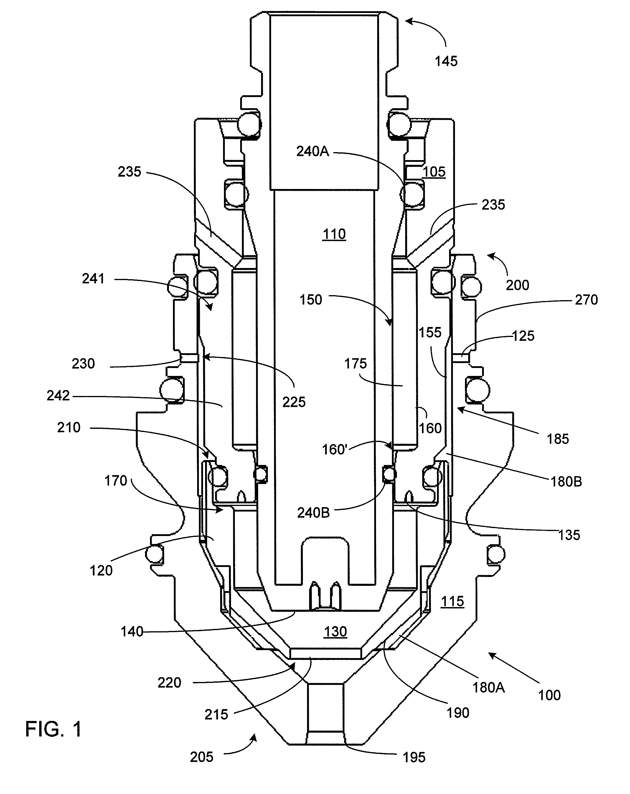
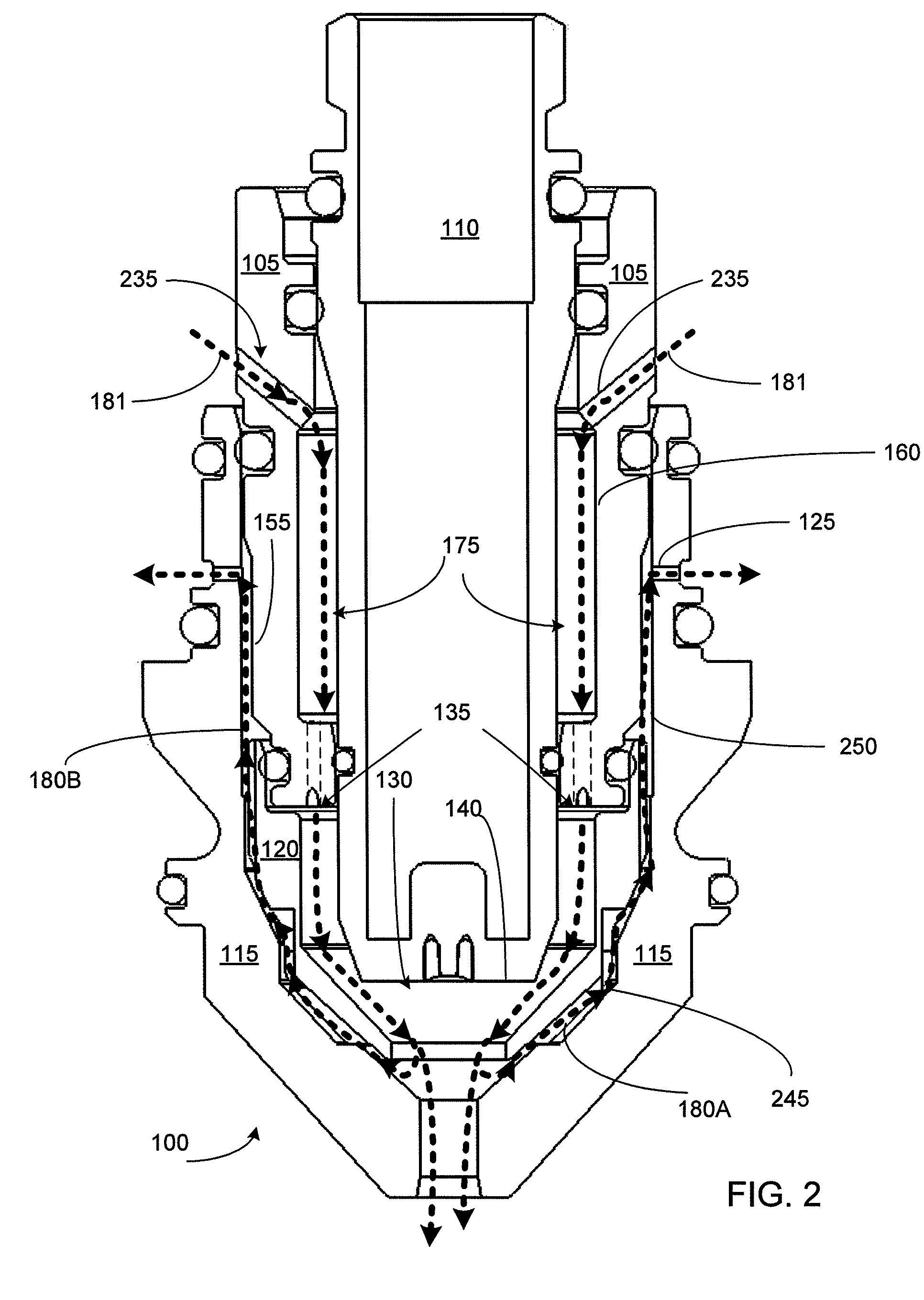
[0032]FIG. 1 shows a stackup of consumables of a plasma arc torch, according to an illustrative embodiment of the invention. A plasma arc torch can include a nozzle 100, swirl ring 105 and electrode 110. The nozzle 100 can include a body 115, a liner 120 disposed within the body 115, and at least one vent passage 125 (e.g., plasma gas vent passage) formed in the body 115. The nozzle 100 can be dimensioned to receive a swirl ring 105, which can be dimensioned to receive an electrode 110. The torch can include a plenum 130 defined, at least in part, by the swirl ring 105, electrode 110 and the nozzle 100. The nozzle 100 can be configured to mate with a swirl ring 105 so that a gas port 135 (e.g., swirl injection point) of the swirl ring 105 can be close to the electrode face 140. Such a configuration allows the use of both a vented nozzle to enhance nozzle life while also having a swirl hole (e.g., gas port 135, swirl injection point) that is close to an electrode face 140 (e.g., resu...


PUM

PropertyMeasurementUnit
lengthaaaaaaaaaa
diameteraaaaaaaaaa
energyaaaaaaaaaa

Abstract

A nozzle for a plasma torch can include a body that has an inner surface, an outer surface, a proximal end, and an exit orifice at a distal end. The nozzle can also include a liner surrounded by the inner surface of the body. The liner can include a proximal end and an exit orifice at a distal end adjacent the exit orifice of the body. The nozzle can include at least one vent passage formed in the body. The vent passage can have an inlet formed in the inner surface of the body and an outlet formed in the outer surface of the body. The vent passage can be disposed between the proximal end of the body and the proximal end of the liner. The plasma arc torch can include a configuration that allows for increased electrode life and nozzle life for a vented high current plasma process.

Description

FIELD OF THE INVENTION[0001]The invention relates in general to the field of plasma arc cutting torches and their method of operation. More specifically, the invention relates to an improved nozzle and related methods of operation.BACKGROUND OF THE INVENTION[0002]In a high current oxygen torch, electrode and nozzle life can be very short as compared with lower current processes. Nozzle life in a high current oxygen torch can be short due to the excessive heat load imparted to the nozzle tip. One method of reducing the heat load on a nozzle and increasing nozzle life is by venting a portion of plasma gas from before the nozzle bore. See, e.g., U.S. Pat. No. 5,317,126 entitled “Nozzle and Method of Operation for a Plasma Arc Torch” filed on Jan. 14, 1992, the contents of which are incorporated by reference in their entirety. Venting further helps constrict the arc by pinching the arc and cooling the nozzle. Vented plasma processes can achieve a more highly constricted arc, which can i...

Claims


Application Information

Patent Timeline
Patent Type & Authority Patents(United States)
IPC IPC(8): B23K10/00
CPCH05H1/28H05H1/34Y10T29/49348
Inventor LIEBOLD, STEPHEN M.CURRIER, BRIAN J.
Owner HYPERTHERM INC
Learn More