
Method and apparatus for a superconducting direct current generator driven by a wind turbine

a superconducting direct current and generator technology, applied in the direction of electric generator control, machines/engines, sustainable buildings, etc., can solve the problems of low torque density of conventional direct drive generators, unsuitable long-life service of gearboxes, and inability to meet the needs of wind turbine towers

Active Publication Date: 2012-12-25
GENERAL ELECTRIC CO
View PDF43 Cites 5 Cited by
  • Summary
  • Abstract
  • Description
  • Claims
  • Application Information

AI Technical Summary

Benefits of technology

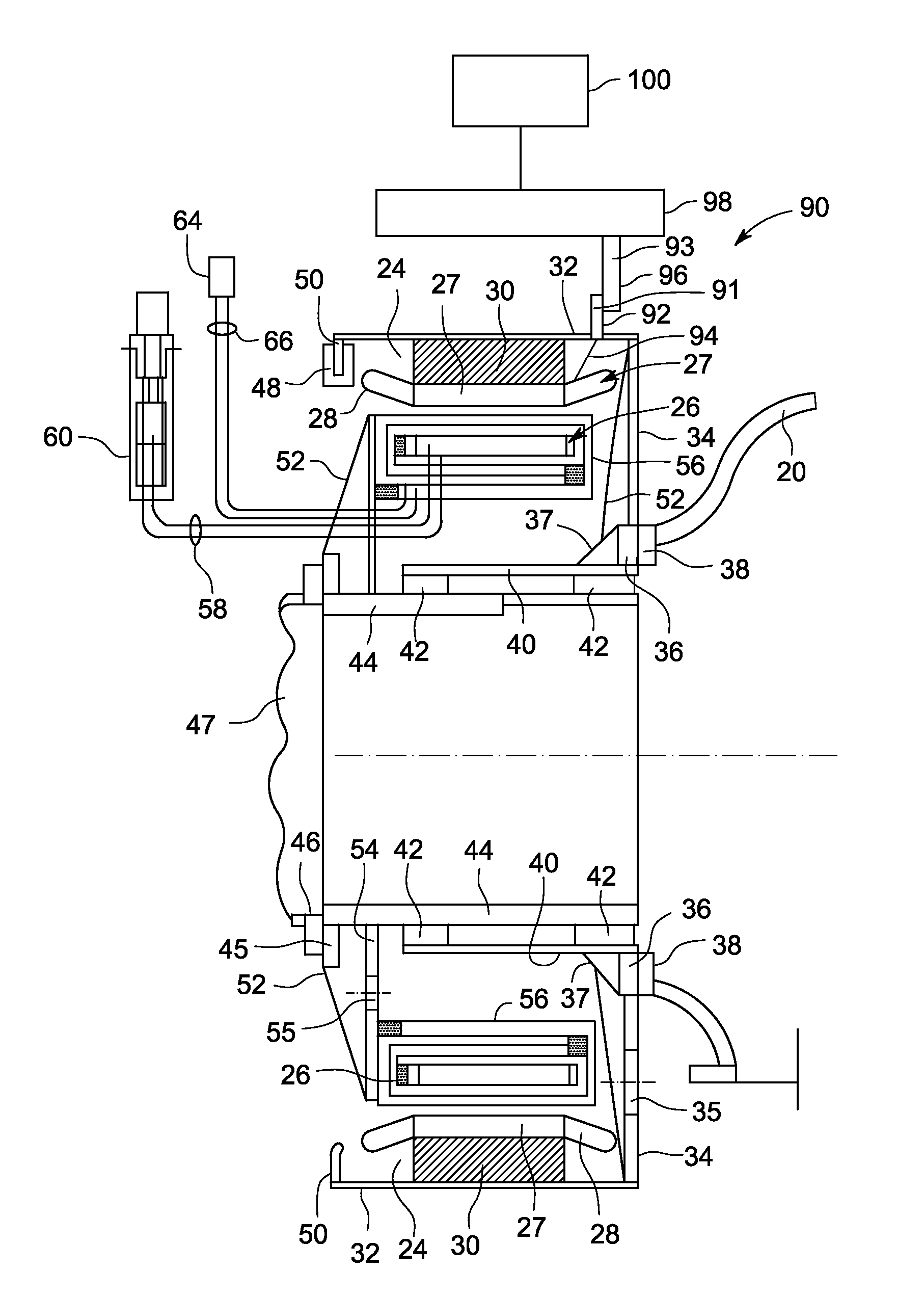
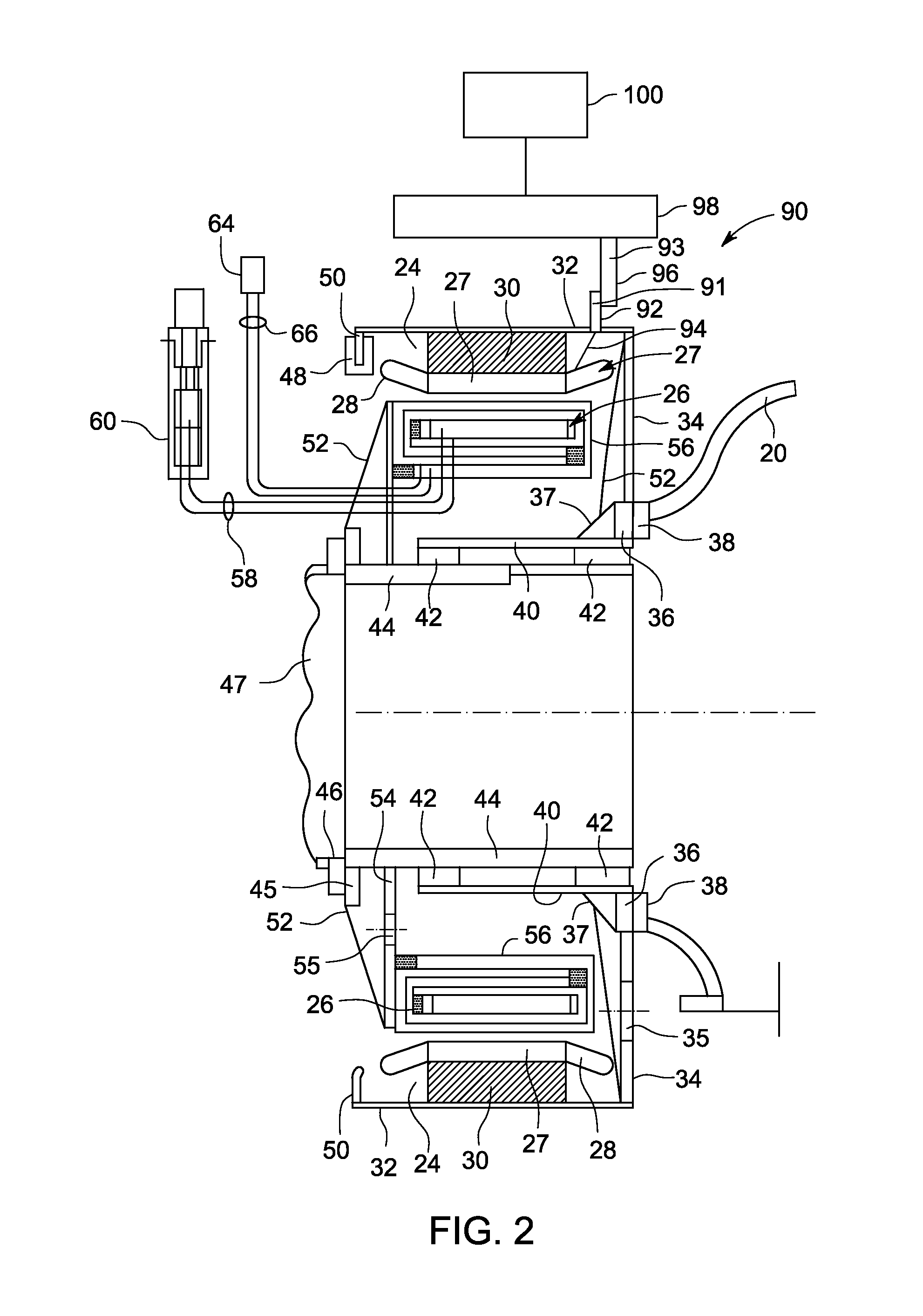
The present patent application describes a superconducting direct current (DC) generator driven by a wind turbine. The generator includes an annular armature, a stationary annular field winding coaxial to the armature and separated by a gap, a non-rotating support for the field winding, a fixed support, and a commutator assembly. The DC generator is mounted on the wind turbine's tower and generates a magnetic field in the non-rotating field winding. The armature is connected to the rotating component of the wind turbine and generates electrical current as it rotates. The DC current is transferred to a power conversion system using the commutator assembly. The superconducting coil magnets are cooled using a cooling liquid that is at least partially vaporized as it cools the coils. The vaporized cooling liquid is condensed in a re-condenser elevated above the DC generator and flows by gravity to the superconducting coil magnets. The technical effects of this patent application include improved efficiency and reliability of wind turbine generators and reduced cooling costs.

Problems solved by technology

Conventional direct drive generators typically have low torque density and become too heavy for a wind turbine tower at power ratings above about 6 MW.
Gearboxes tend to be unreliable and not suitable for long life service in a wind turbine tower.

Method used


Image

  • Method and apparatus for a superconducting direct current generator driven by a wind turbine
  • Method and apparatus for a superconducting direct current generator driven by a wind turbine
  • Method and apparatus for a superconducting direct current generator driven by a wind turbine

Examples


Embodiment Construction

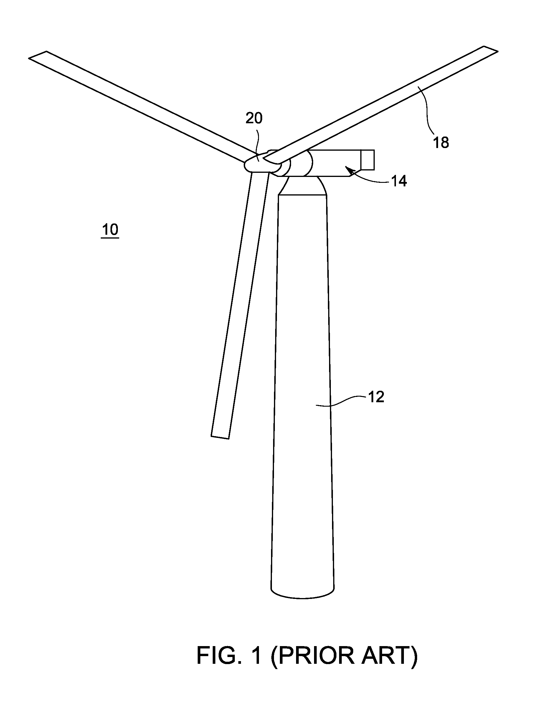
[0018]A superconducting direct current (DC) generator has been developed with a stationary, or non-rotating, field winding and a rotating armature driven directly by a turbine, such as a wind turbine. The superconducting DC generator may be mounted in the upper region of wind turbine tower and coupled directly to the rotating component of the wind turbine, e.g., the blades. The direct drive generator is sufficiently lightweight to be mounted on top of a conventional wind turbine tower and coupled to conventional rotating wind turbine blades.

[0019]The superconducting DC generator provides high torque density, which allows the DC generator to be lightweight, despite the added components needed to cool and insulate the superconducting coils in the field winding. The stationary field winding includes a series of racetrack shaped superconducting coils cooled to cryogenic temperatures. The rotating armature and iron yoke (optional) are connected directly to and turned by the wind turbine....


PUM


Abstract

A direct current generating including an annular armature connectable to rotate with a rotating component of a wind turbine and a stationary annular field winding coaxial to the armature and separated by a gap from the armature. The field winding is configured to include superconducting coil magnets and a support structure connectable to an upper region of a tower of the wind turbine. The direct current generator further including a commutator assembly configured to transfer DC current generated by the rotating armature to a power conversion system.

Description

BACKGROUND[0001]This invention relates to electrical generators and, particularly, relates to wind turbines and superconducting direct current (DC) generators.[0002]A direct drive generator driven by the blades of the wind turbine is efficient and has minimal losses due to transmission of torque from the turbine blades to the DC generator. Direct drive conventional generators on wind turbine towers generally have a power rating of 6 megawatts (MW) or less.[0003]Conventional direct drive generators typically have low torque density and become too heavy for a wind turbine tower at power ratings above about 6 MW. Gearboxes tend to be unreliable and not suitable for long life service in a wind turbine tower.[0004]In addition, alternating current (AC) wind generators must undergo total power conversion to convert the generated power to 50-60 cycle AC at a particular voltage desired by the grid connection. This conversion is typically accomplished by a power electronics (PE) converter con...

Claims


Application Information

Patent Timeline
Patent Type & Authority Patents(United States)
IPC IPC(8): F03D9/00H02P9/04H02K9/00
CPCF03D9/002F03D11/028H02K7/1838H02K13/006H02K55/00F03D7/0248H02K23/12F05B2220/7062F05B2220/7066Y02E10/723Y02B10/30Y02E10/722Y02E10/725Y02E40/62F03D9/25F03D15/20H02K55/02Y02E10/72Y02E40/60
Inventor BRAY, JAMES WILLIAM
Owner GENERAL ELECTRIC CO
Learn More