X-ray diffraction method and X-ray diffraction apparatus

a diffraction method and a technology of x-ray diffraction, applied in material analysis using wave/particle radiation, instruments, nuclear engineering, etc., can solve the problems of reducing x-ray intensity but being severe in angular resolution, reducing x-ray intensity by a large amount, and a structure that places plural analyzer crystals and plural x-ray detectors around a sample. , the effect of less x-ray intensity reduction

Inactive Publication Date: 2012-12-25
RIGAKU CORP
View PDF7 Cites 14 Cited by
  • Summary
  • Abstract
  • Description
  • Claims
  • Application Information

AI Technical Summary

Benefits of technology

[0010]It is an object of the present invention to provide an X-ray diffraction method and apparatus, which is superior in angular resolution, small in X-ray intensity reduction, and simple in structure as compared to the prior art using plural analyzer crystals and as many X-ray detectors.
[0011]It is another object of the present invention to provide an X-ray diffraction method and apparatus, which can restrain X-ray intensity reduction with remaining good angular resolution even when the width of an incident X-ray beam is comparatively large.
[0012]It is further another object of the present invention to provide an X-ray diffraction method and apparatus, in which when a reflective surface consists of a combination of plural flat reflective surfaces, adverse effects on measurement can be minimized, the adverse effects being that different reflected X-rays coming from adjacent flat reflective surfaces might be mixed each other.
[0017]The present invention has an advantage that a combination of an analyzer crystal having a reflective surface with the predetermined shape and a single, one-dimensional position-sensitive X-ray detector brings a superior angular resolution, less reduction of an X-ray intensity, and a simple structure as compared to the prior art using plural analyzer crystals.
[0018]In addition, even when the width of an X-ray beam that is incident on a sample is comparatively large, the use of the mirror having a shape based on a new mathematical equation brings prevention of angular resolution reduction caused by X-ray optical aberration and prevention of X-ray intensity reduction, so that both a superior angular resolution and a superior X-ray intensity gain are attained.
[0019]Furthermore, with the present invention, when a reflective surface consists of a combination of plural flat reflective surfaces, adverse effects on measurement can be minimized, the adverse effects being that different reflected X-rays coming from adjacent flat reflective surfaces might be mixed each other.

Problems solved by technology

The method with the long parallel slit is not so severe in X-ray intensity reduction but is inferior in angular resolution.
On the contrary, the method with the analyzer crystal is superior in angular resolution but is severe in X-ray intensity reduction.
The structure that places plural analyzer crystals and plural X-ray detectors around a sample as disclosed in the first and second publications is so complex and expensive that it is hardly applicable to an X-ray diffraction method in a laboratory system.

Method used


Image

  • X-ray diffraction method and X-ray diffraction apparatus
  • X-ray diffraction method and X-ray diffraction apparatus
  • X-ray diffraction method and X-ray diffraction apparatus

Examples


Embodiment Construction

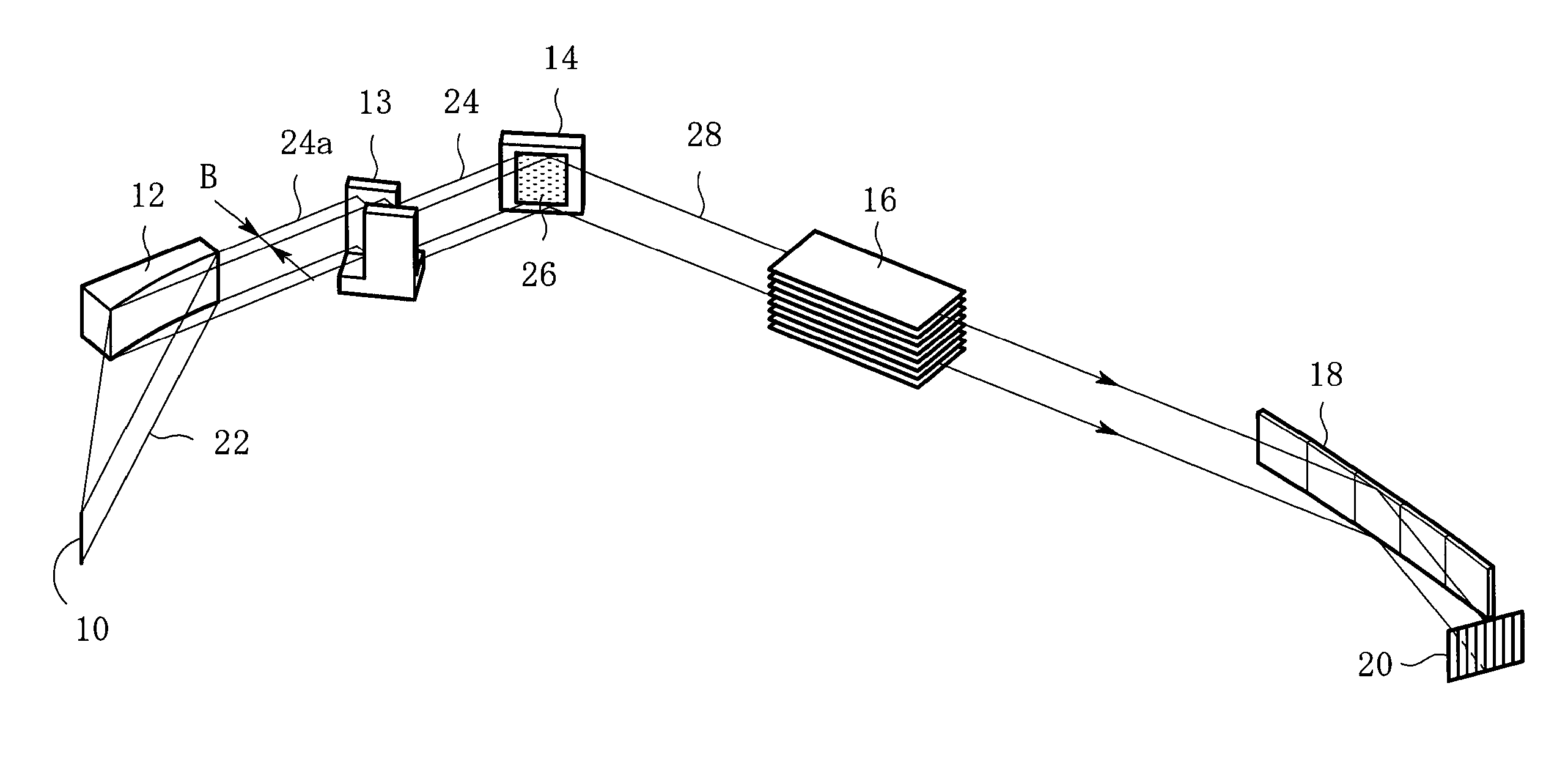
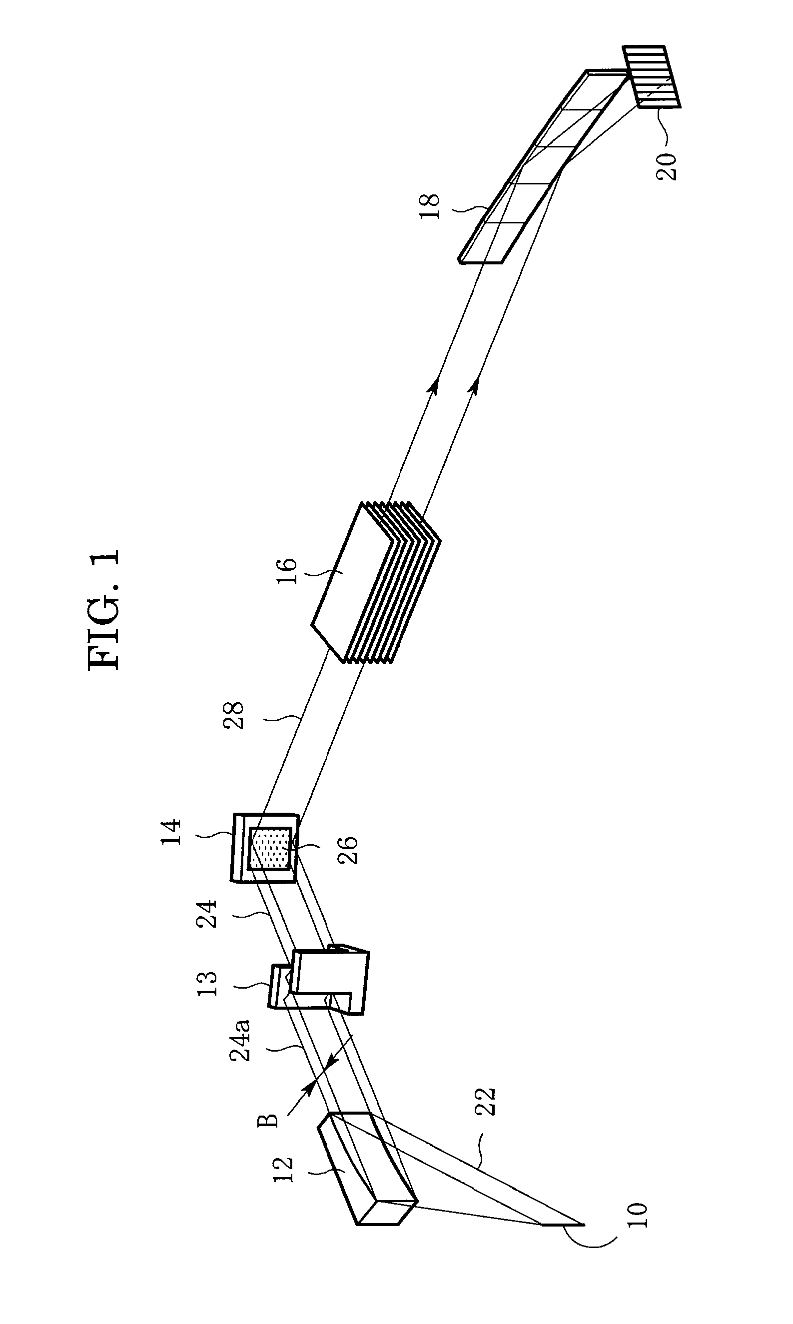
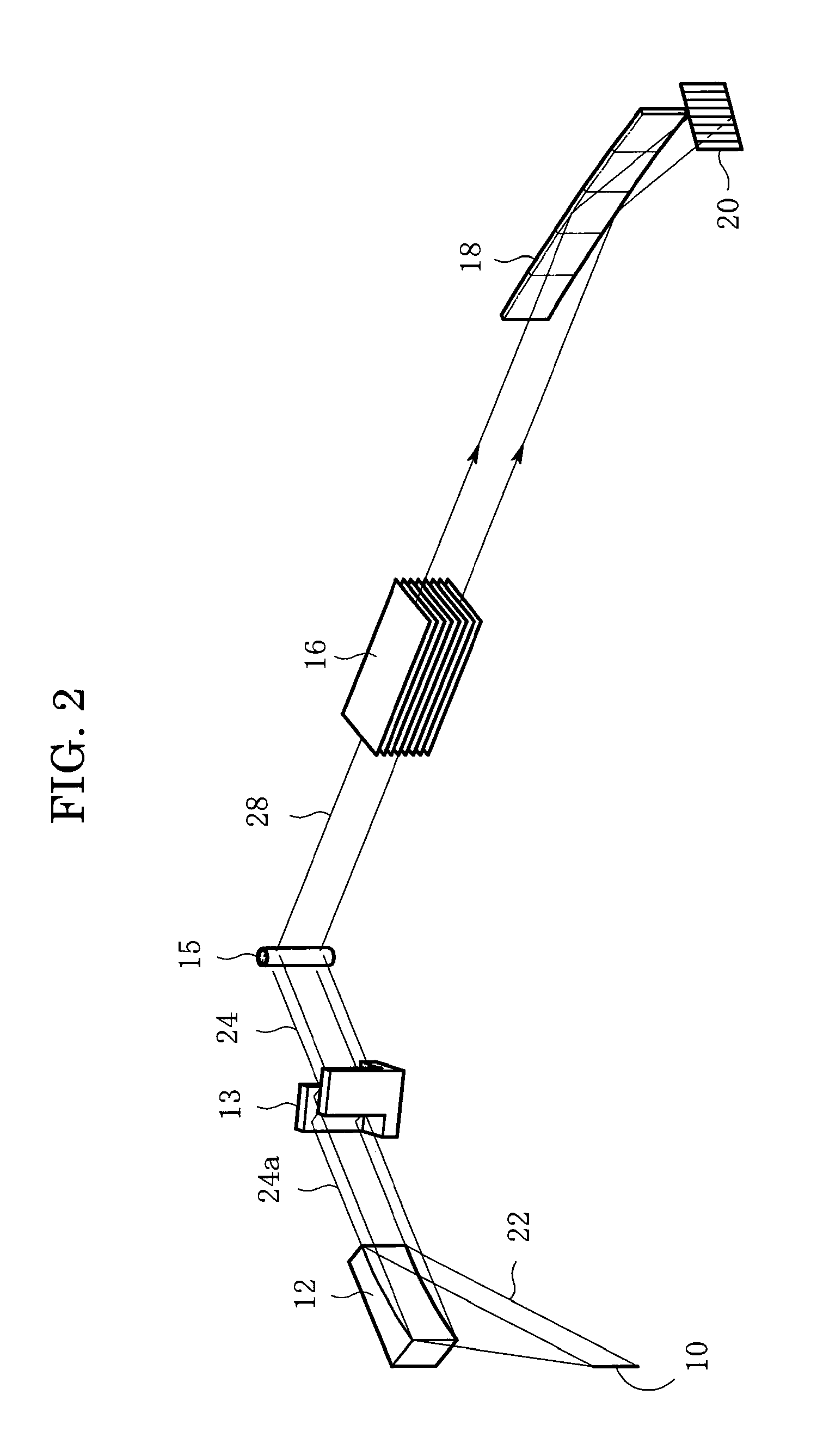
[0057]Embodiments of the present invention will now be described in detail below with reference to the drawings. FIG. 1 is a schematic perspective view of an apparatus for carrying out an X-ray diffraction method according to the present invention. The X-ray diffraction apparatus comprises an X-ray source having a linear (or point-like) X-ray focus 10, a multilayer mirror 12 having a parabolic-shaped reflective surface, a channel cut monochromator 13 for selecting a characteristic X-ray Kα1, a sample holder 14, a Soller slit 16 for restricting vertical divergence of diffracted X-rays, a mirror 18 made of an analyzer crystal, and a one-dimensional position-sensitive X-ray detector 20. FIG. 1 shows the case using a linear X-ray focus. A divergent beam 22, which consists of X-rays emitted from the X-ray focus 10, is converted into a parallel beam 24a by the multilayer mirror 12 having a parabolic reflective surface. The multilayer mirror 12 is optimized for the X-ray wavelength to be u...


PUM

PropertyMeasurementUnit
widthaaaaaaaaaa
lengthaaaaaaaaaa
lengthaaaaaaaaaa

Abstract

In an X-ray diffraction method, an X-ray parallel beam is incident on a sample, and diffracted X-rays from the sample are reflected at a mirror and thereafter detected by an X-ray detector. The reflective surface of the mirror is a combination of plural flat reflective surfaces, the respective centers of which are located on an equiangular spiral having a center that is located on a surface of the sample. The X-ray detector is one-dimensional position-sensitive in a plane parallel to the diffraction plane. X-rays that have been reflected at different flat reflective surfaces reach different points on the X-ray detector respectively. A correction is performed for separately recognizing different reflected X-rays that may have been reflected at the different flat reflective surfaces, and might be mixed with each other on the same detecting region of the X-ray detector.

Description

BACKGROUND OF THE INVENTION[0001]The present invention relates to an X-ray diffraction method and an X-ray diffraction apparatus with the use of the parallel beam method.[0002]In the powder X-ray diffraction method for powder samples, thin film samples or polycrystalline samples, an analyzer must be inserted into a diffracted-beam-side optical system (i.e., a receiving optical system) in order to improve the angular resolution when using the parallel beam method. One of known analyzers is a long parallel slit that has a narrow angle of X-ray aperture, and the other is an analyzer crystal. The method with the long parallel slit is not so severe in X-ray intensity reduction but is inferior in angular resolution. On the contrary, the method with the analyzer crystal is superior in angular resolution but is severe in X-ray intensity reduction. Therefore, in the parallel beam method, there is desired a suitable analyzer that is superior in angular resolution and is small in X-ray intensi...

Claims


Application Information

Patent Timeline
Patent Type & Authority Patents(United States)
IPC IPC(8): G01N23/20
CPCB82Y10/00G01N23/207G21K2201/061G21K2201/062
Inventor TORAYA, HIDEOKONAKA, HISASHI
Owner RIGAKU CORP
Why Eureka
Try Eureka