Sheet conveying apparatus and image forming apparatus

a conveying apparatus and forming apparatus technology, applied in the direction of electrographic process, transportation and packaging, instruments, etc., can solve the problems of reducing increasing the amount of abrasion of the guide, and unable to suppress the flutter of the sheet, so as to prevent the reduction of the detection accuracy of the detecting means

Inactive Publication Date: 2012-12-25
CANON KK
View PDF21 Cites 12 Cited by
  • Summary
  • Abstract
  • Description
  • Claims
  • Application Information

AI Technical Summary

Benefits of technology

[0008]The present invention is made in view of the above-mentioned circumstances, and an object of the present invention is to provide a sheet conveying apparatus and an image forming apparatus which can prevent reduction of the detection accuracy of the detecting means.
[0010]As force from a sheet which is conveyed through the sheet conveying path moves the holding member configured to hold the pressure member according to the present invention, the reduction in the detection accuracy of the detection unit can be prevented at a low cost.

Problems solved by technology

If the guide is abraded in this way, the amount of abrasion of the guide increases as the number of sheets which passes increases, and there is a fear in that, ultimately, the position of the sheet is away from the focal position of the sensor or the flutter of the sheet cannot be suppressed.
As a result, the detection accuracy of the detecting means is reduced.

Method used


Image

  • Sheet conveying apparatus and image forming apparatus
  • Sheet conveying apparatus and image forming apparatus
  • Sheet conveying apparatus and image forming apparatus

Examples


first embodiment

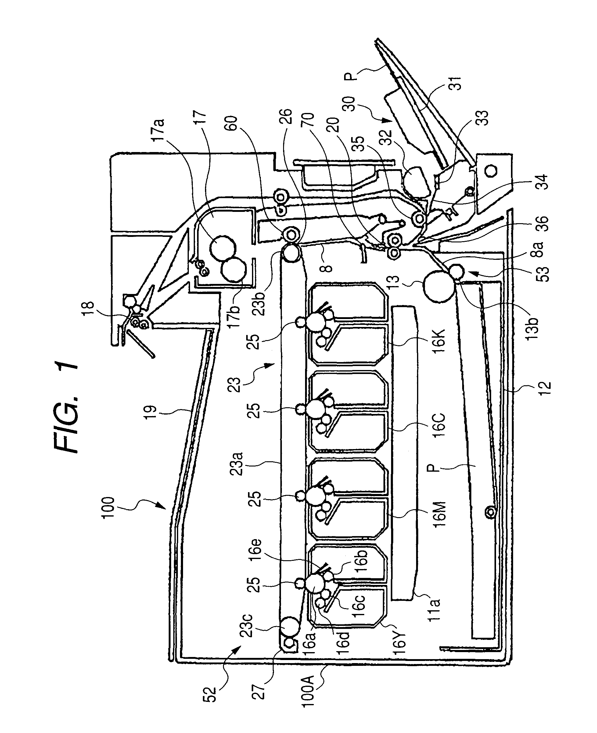
[0024]Embodiments of the present invention are described in detail in the following with reference to the attached drawings. FIG. 1 illustrates a schematic structure of a sheet conveying apparatus according to the present invention and a full color laser beam printer as an example of an image forming apparatus including the sheet conveying apparatus. FIG. 1 illustrates a full color laser printer 100 and a full color laser printer main body (hereinafter referred to as an apparatus main body) 100A. The apparatus main body 100A includes an image forming portion 52 configured to form an image on a sheet, a sheet feeding apparatus 53 configured to feed a sheet, and a fixing portion 17 configured to fix a toner image formed on the sheet.

[0025]The image forming portion 52 includes process cartridges 16 (16Y, 16M, 16C, 16K) which are detachably mounted in the apparatus main body 100A to form toner images of four colors of yellow, magenta, cyan, and black, respectively, each process cartridg...

second embodiment

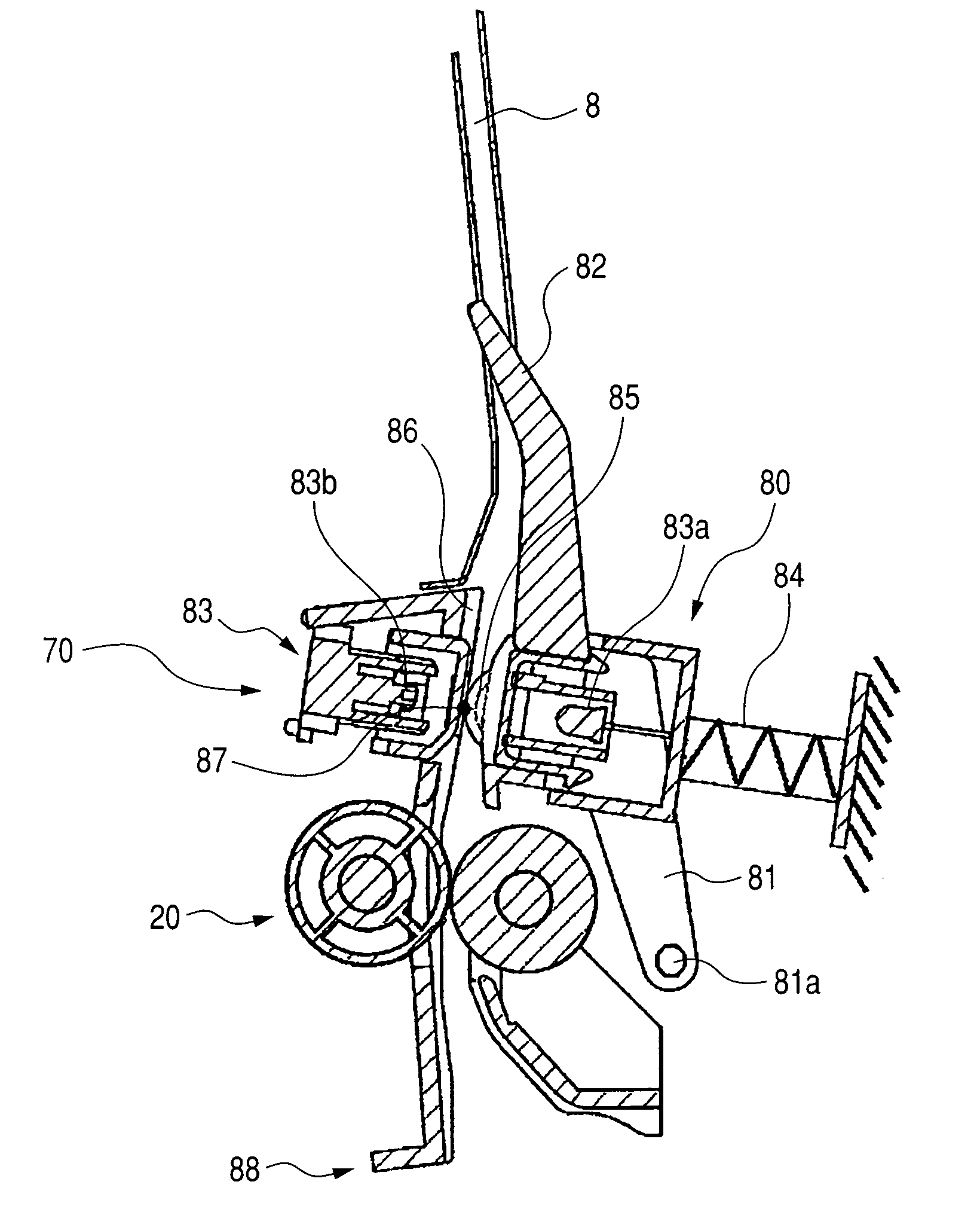
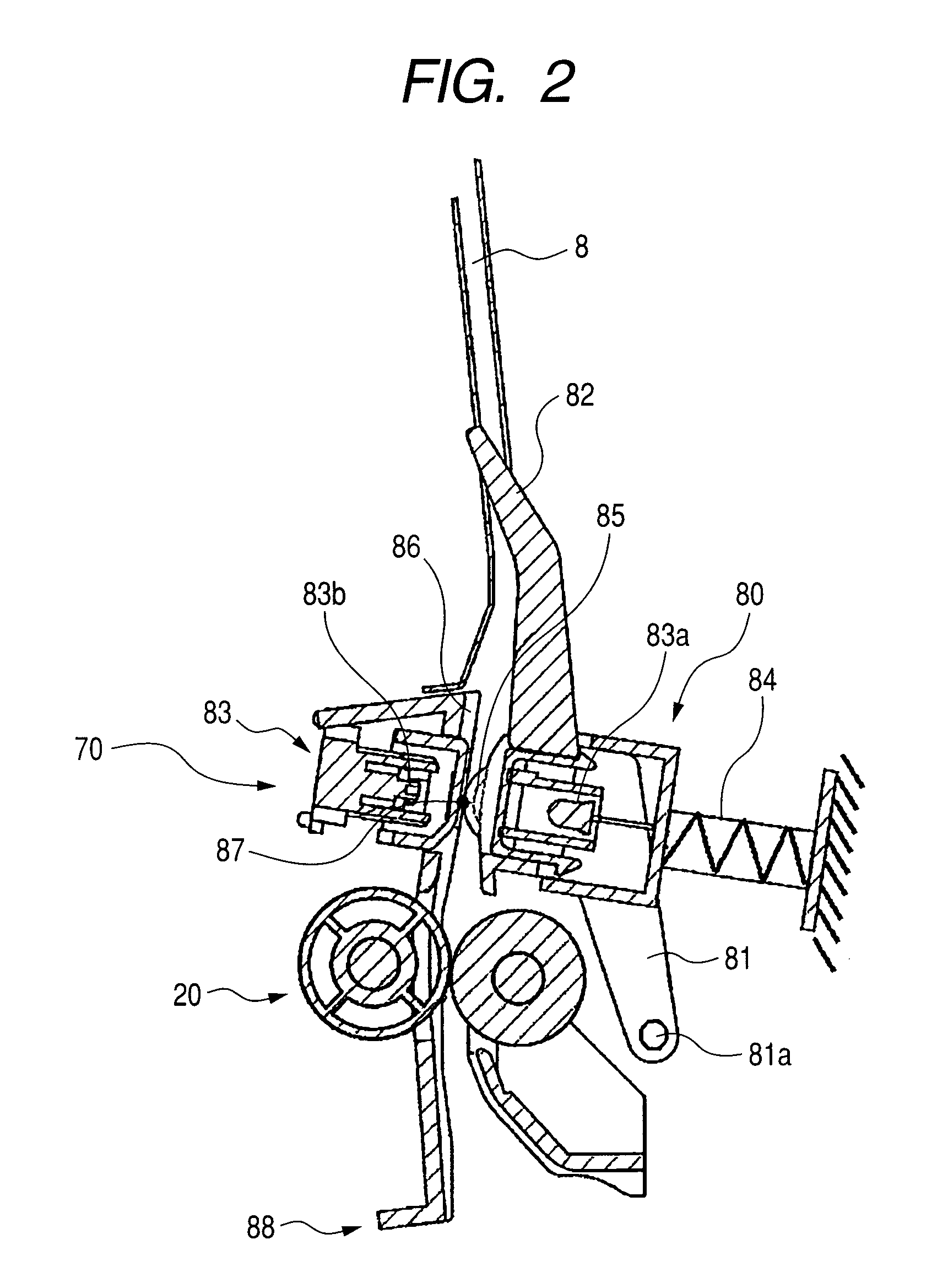
[0041]Next, the present invention will be described. FIG. 6 illustrates a structure of a conveyance unit as a sheet conveying apparatus according to this embodiment. It is to be noted that, in FIG. 6, reference symbols which are the same as those in FIG. 2 designate the same or corresponding members as those of FIG. 2. In FIG. 6, a sheet pressure-contact rotatable member urging spring 89 is an urging member for urging the pressure-contact rotatable members 85 to the guide surface side of the guide member 86 which is on the guide member side. The sheet pressure-contact rotatable member urging spring 89 is disposed between the pressure-contact rotatable members 85 and the pivotable member 81. The pressure-contact rotatable members 85 are urged by the sheet pressure-contact rotatable member urging spring 89 so as to be in pressure contact with the guide surface 86a disposed so as to be opposed to the pressure-contact rotatable members 85 with the sheet conveying path 8 interposed there...

third embodiment

[0043]Next, the present invention will be described. FIG. 8 illustrates a structure of a conveyance unit as a sheet conveying apparatus according to this embodiment. It is to be noted that, in FIG. 8, reference symbols which are the same as those in FIG. 2 designate the same or corresponding members illustrated in FIG. 2. In FIG. 8, a pressure-contact reducing flag 300 in this embodiment as a moving member is movably held by a conveyance guide on the guide member side. As illustrated in FIGS. 9 and 10, an abutting portion 301 for intersecting the sheet conveying path 8 is provided at a center portion in a width direction of a flag main body 300a of the pressure-contact reducing flag 300. Further, pushing portions 302 which abut upper end portions 81c of the pivotable members 81 urged by the compression spring 84 is provided at both end portions of the flag main body 300a in the width direction thereof outside the sheet P.

[0044]Next, a sheet conveying operation of the conveyance unit...


PUM

PropertyMeasurementUnit
pressureaaaaaaaaaa
pressure forceaaaaaaaaaa
thicknessaaaaaaaaaa

Abstract

A sheet conveying apparatus including: a sheet conveying path through which a sheet is conveyed; a sensor unit configured to output a signal according to a characteristic of the sheet which is conveyed through the sheet conveying path; a pressure unit configured to press the sheet against the sensor unit; and a moving member protruding into the sheet conveying path, the moving member being moved by being pushed by the sheet passing through the sheet conveying path, wherein the pressure unit is interlocked with the moving member so that the sheet is pressed by the pressure unit against the sensor unit when the moving member is not pushed by the sheet, and a pressure force on the sheet applied by the pressure unit is released or reduced when the moving member is pushed by the sheet.

Description

BACKGROUND OF THE INVENTION[0001]1. Field of the Invention[0002]The present invention relates to a sheet conveying apparatus and an image forming apparatus.[0003]2. Description of the Related Art[0004]There is an image forming apparatus in which a sheet discriminating device such as an optical sensor is provided for automatically discriminating the type of a sheet (see Japanese Patent Application Laid-Open No. 2008-94600). A technology for controlling development conditions, transfer conditions, fixing conditions, or the like according to the discriminated type of the sheet is proposed (see Japanese Patent Application Laid-Open No. 2006-175611).[0005]Further, conventionally, in a color laser printer, for example, single-color tone patches of yellow (Y), magenta (M), cyan (C), and black (K) or patches of colors made by mixing C, M, and Y are formed on a sheet. Further, density or chromaticity of the patches on the sheet is detected by an optical sensor after the patches are fixed. Fu...

Claims


Application Information

Patent Timeline
Patent Type & Authority Patents(United States)
IPC IPC(8): G03G15/00
CPCB65H7/02G03G15/6564B65H2404/1521B65H2511/20B65H2511/414B65H2511/416B65H2801/06G03G2215/00409G03G2215/00616G03G2215/00738G03G2215/00751B65H2301/44324G03G15/235B65H2220/01B65H2220/08B65H2220/02B65H2220/11B65H2220/03
Inventor NAKAJIMA, KEITAKUWATA, TAKASHI
Owner CANON KK
Why Eureka
Try Eureka