Oil sensor placement structure of engine

A technology for configuring structure and engine oil, applied in the direction of engine components, machines/engines, mechanical equipment, etc., can solve the problem of difficulty in ensuring the required space, and achieve the effect of preventing the detection accuracy from being reduced

Inactive Publication Date: 2009-06-03
HONDA MOTOR CO LTD
View PDF2 Cites 5 Cited by
  • Summary
  • Abstract
  • Description
  • Claims
  • Application Information

AI Technical Summary

Problems solved by technology

When the balancer device is arranged inside the oil pan, if the recess is formed on the oil pan for the passage of the air supply and exhaust pipes, it may be difficult to securely arrange the oil sensor inside the oil pan due to the recess. Possibility of required space

Method used


Image

  • Oil sensor placement structure of engine
  • Oil sensor placement structure of engine
  • Oil sensor placement structure of engine

Examples


Embodiment 1

[0054] Figure 1 to Figure 8 The first embodiment of the present invention is shown.

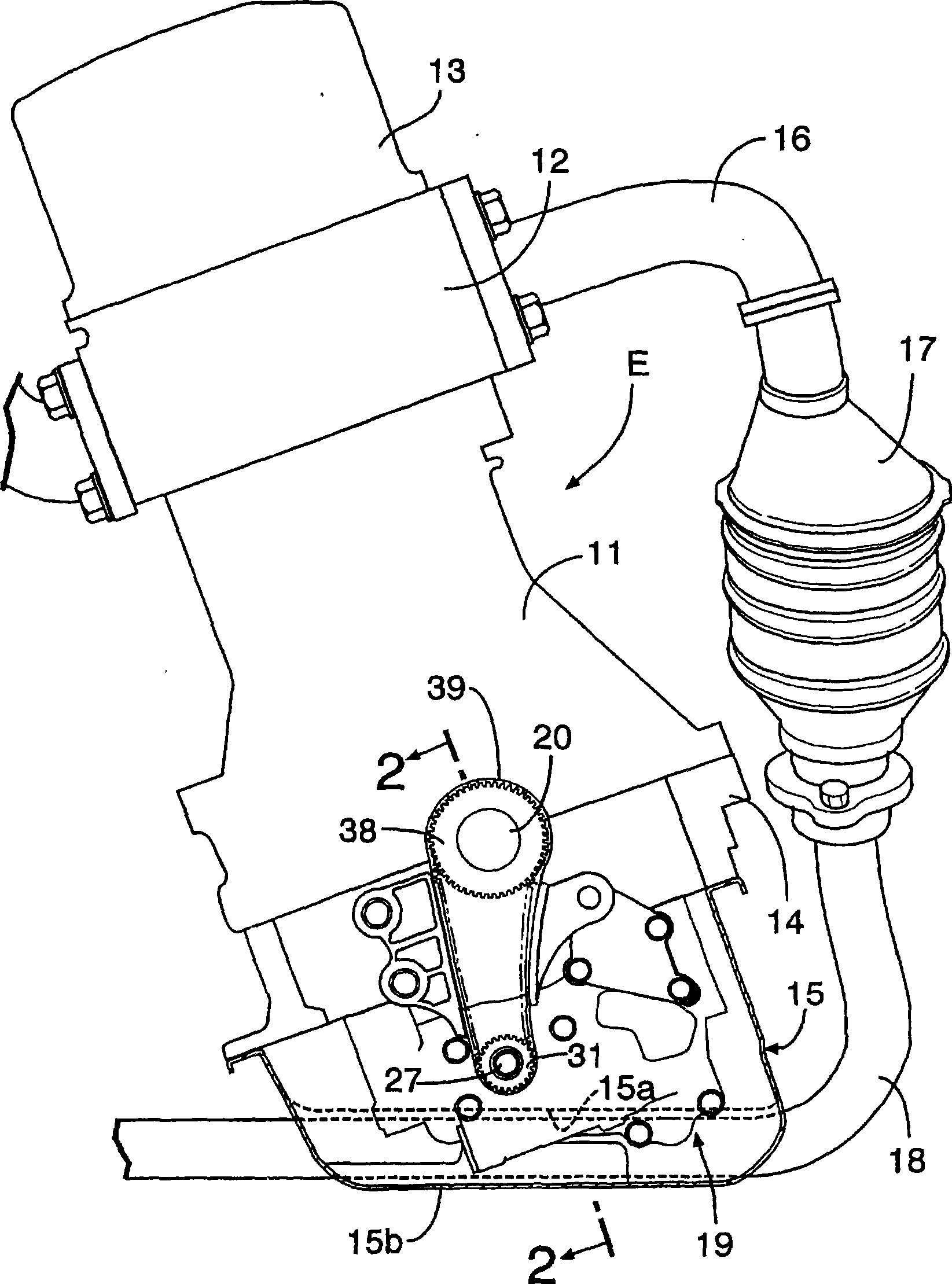
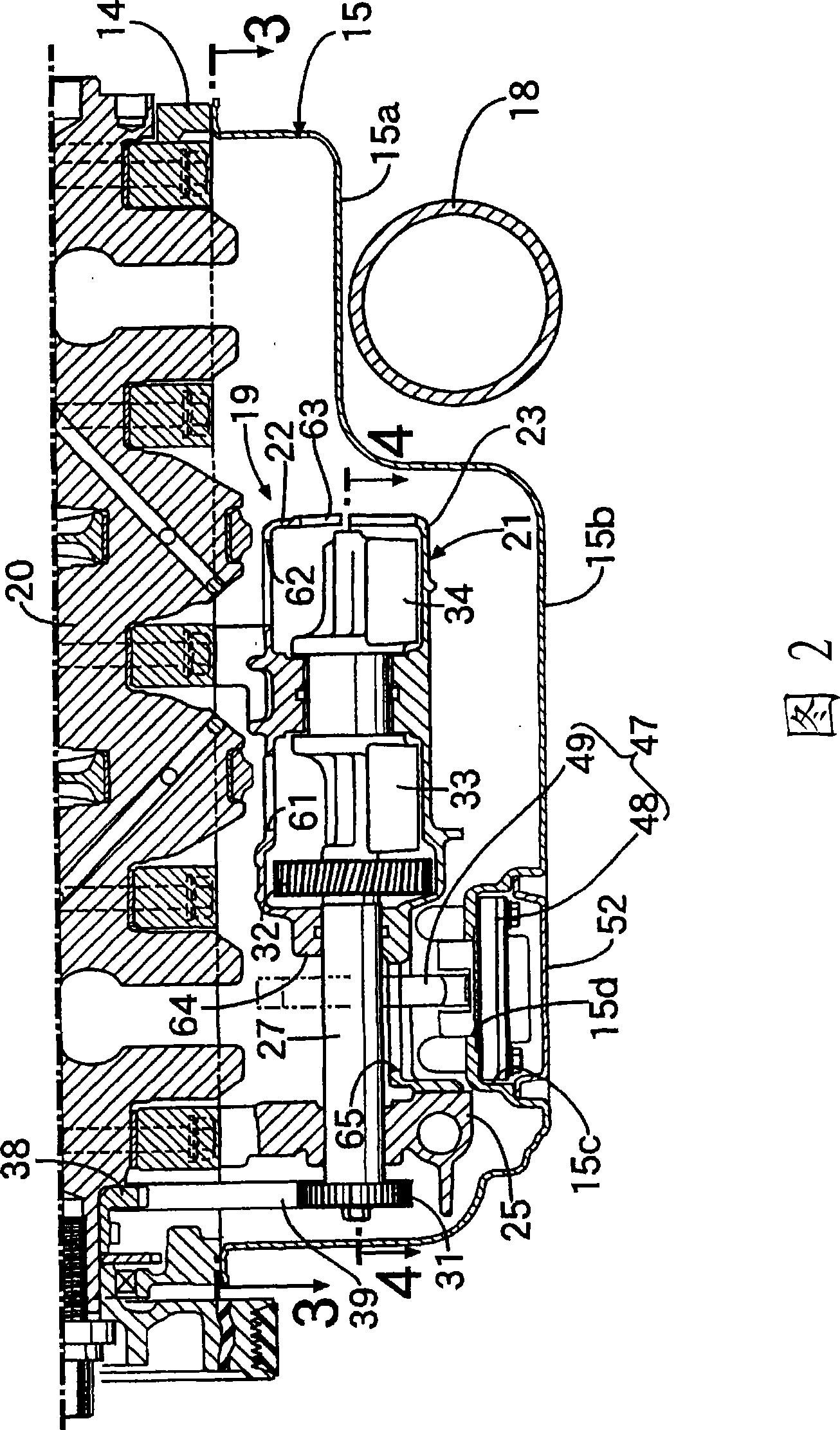
[0055] Depend on figure 1 As can be seen, the cylinder block 11 of the diesel engine E mounted horizontally in the engine room of a motor vehicle has a cylinder head 12 and a cylinder head cover 13 coupled to its upper portion, and a crankcase 14 and an oil pan 15 coupled to its lower portion. The exhaust pipe 18 connected to the exhaust manifold 16 via the DPF (diesel particulate filter) 17 passes through the lower surface of the oil pan 15 and extends to the rear of the vehicle body. The exhaust manifold 16 combines On the front surface of the cylinder head 12 . A secondary balancer device 19 for reducing secondary vibration of the engine E is provided between the lower surface of the cylinder block 11 and the oil pan 15 . The crankshaft 20 is rotatably supported on a dividing surface between the cylinder block 11 and the crankcase 14 .

[0056] Next, the configuration of the secondary...

Embodiment 2

[0077] Next, a second embodiment of the present invention will be described with reference to FIG. 9 .

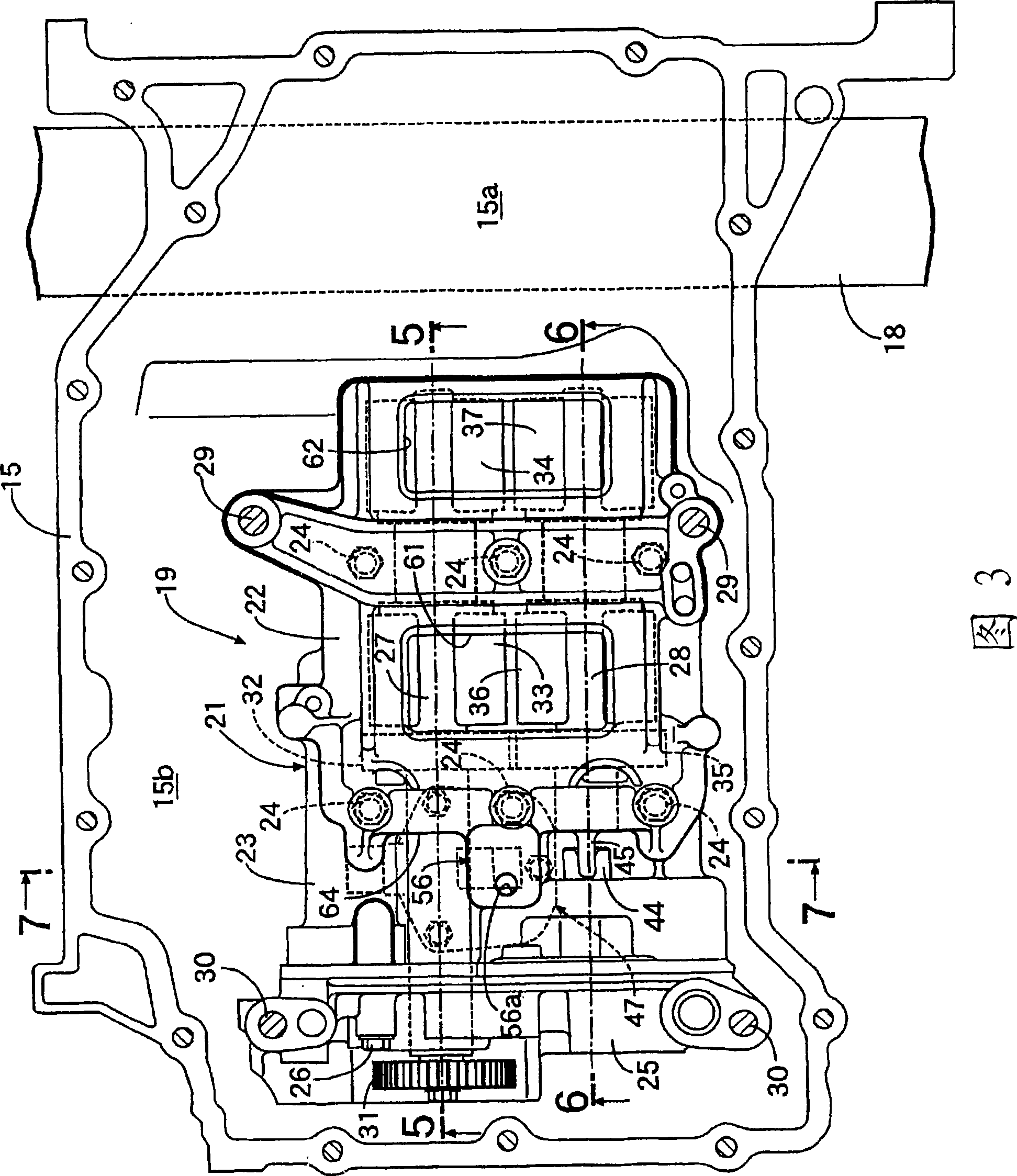
[0078] In the first embodiment, the shielding portion 56 is integrally formed with the upper case 22 , but in the second embodiment, the shielding portion 56 is constituted as an independent component, and is assembled to the lower case of the balancer case 21 with bolts 57 , 57 . The lower surface of the opening 65 of 23. The shielding portion 56 is a cylindrical member tapered from the lower portion toward the upper portion, and covers substantially the entire sensing portion 49 of the oil level sensor 47 protruding into the oil pan 15 .

[0079]In this manner, by covering substantially the entirety of the sensor portion 49 with the shield portion 56 , the influence of the splash of engine oil can be more reliably eliminated, and the detection accuracy of the oil level sensor 47 can be further improved. In addition, when the oil pan 15 is detached from the crankcase 14 i...


PUM


Abstract

The present invention provides oil sensor placement structure of engine. In an engine, an oil level sensor (47) provided at the bottom of an oil pan (15) that contains engine oil and upstanding upward in the vertical direction is placed between a pair of balancer shafts (27, 28) that are received in parallel to each other in a balancer housing (21) provided between the lower surface of a cylinder block and the oil pan (15). A dead space formed between the pair of balancer shafts (27, 28) is effectively used to allow the oil level sensor (47) to be compactly received. Also, the pair of balancer shafts (27, 28) suppress agitation of the engine oil to prevent degradation of detection accuracy caused by splash of the oil on the oil level sensor (47).

Description

technical field [0001] The present invention relates to an arrangement structure of an oil sensor in an engine having a balancer housing for accommodating a pair of balance shafts parallel to each other between the lower surface of a cylinder block and an oil pan storing engine oil. Background technique [0002] The following Patent Document 1 discloses a technique in which an oil deterioration sensor that detects the degree of deterioration of engine oil based on a pH value is provided on the bottom of an oil pan in order to determine the engine oil replacement timing of a motor vehicle engine. This oil deterioration sensor has: a sensing part in which a sensing element is housed; fixed at the bottom of the oil pan. [0003] Furthermore, the following Patent Document 2 discloses a technique in which a baffle plate is provided above the engine oil to suppress the liquid surface swell of the engine oil stored in the engine oil pan. [0004] Patent Document 1: Japanese Paten...

Claims


Application Information

Patent Timeline
Patent Type & Authority Applications(China)
IPC IPC(8): F01M11/12F02B77/00
CPCF01M11/12F02B75/06
Inventor 小山良明上嶋英夫远藤祐介
Owner HONDA MOTOR CO LTD
Why Eureka
Try Eureka