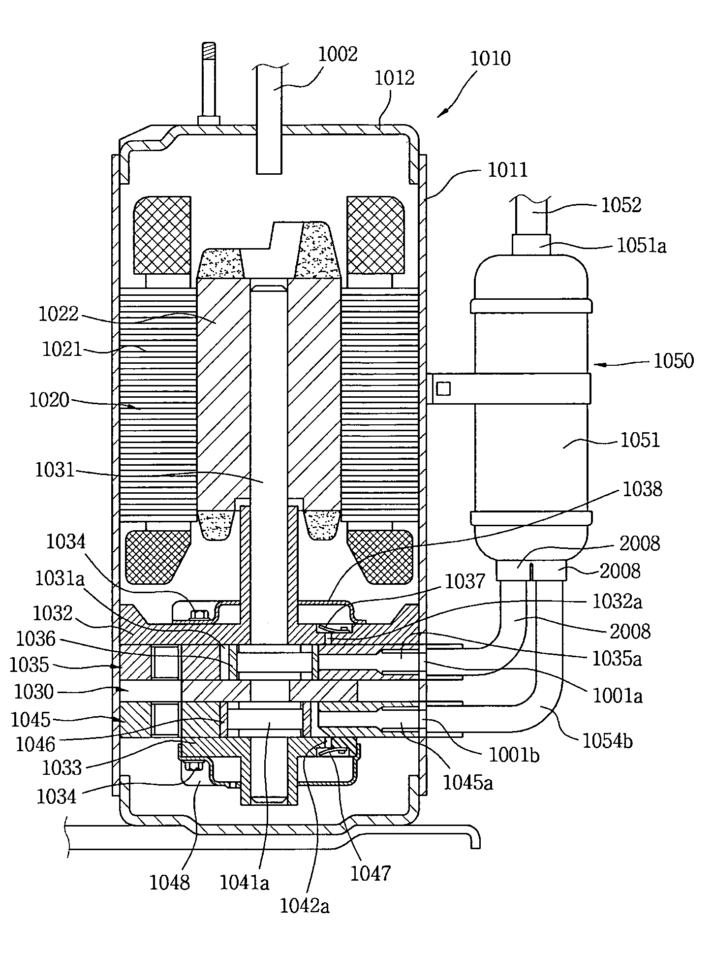
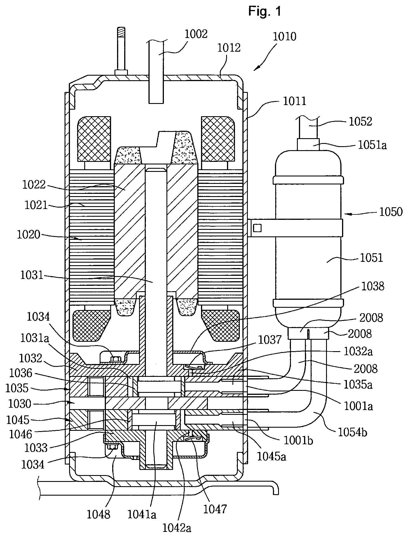
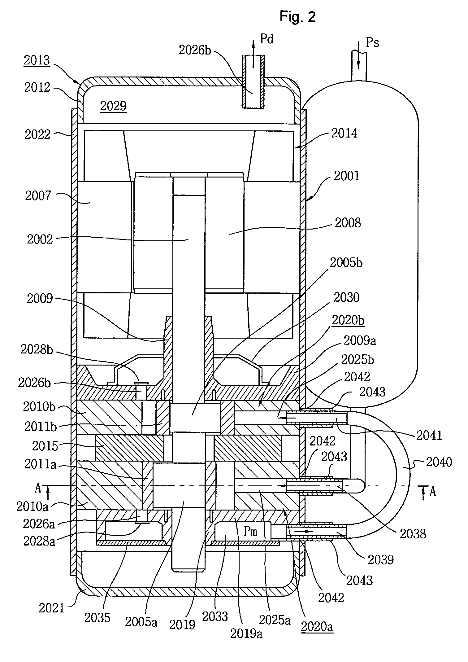
2 stage rotary compressor

a compressor and rotary technology, applied in the direction of machines/engines, rotary/oscillating piston pump components, liquid fuel engines, etc., can solve the problem of reducing the noise spectrum of compressors, and achieve the effect of suppressing the noise of compressors

Active Publication Date: 2013-01-01
LG ELECTRONICS INC
View PDF5 Cites 7 Cited by
  • Summary
  • Abstract
  • Description
  • Claims
  • Application Information

AI Technical Summary

Benefits of technology

[0032]According to a 2 stage rotary compressor of the present invention, an area of a third discharge port discharging high pressure refrigerant compressed in a 2 stage compression assembly to a hermetic container can be optimized to suppress noise of the compressor.
[0033]In addition, according to a 2 stage rotary compressor of the present invention, an area of a third discharge port has a ratio within a predetermined range with respect to an area of a first discharge port discharging refrigerant compressed in a low pressure compression assembly. Therefore, the area of the third discharge port can be optimized, corresponding to the area of the first discharge port determining the entire compression capability of the 2 stage compressor.

Problems solved by technology

Accordingly, a volume flow of refrigerant discharged in a discharge stroke of a 2 stage compression assembly of the 2 stage rotary compressor, and the area of the discharge port of the muffler are not optimized to thereby entirely increase a noise spectrum.

Method used


Image

  • 2 stage rotary compressor
  • 2 stage rotary compressor
  • 2 stage rotary compressor

Examples


third embodiment

[0066]The low pressure vane 124 and the high pressure vane (not shown) are positioned on the same axis. Accordingly, the middle pressure communication hole 161a formed in the lower bearing 161 and the middle pressure inflow groove 130a formed in the high pressure cylinder 131 are not formed on the same axis, but spaced apart from each other in a horizontal direction. According to the present invention, the middle pressure communication hole 120a of the low pressure cylinder 121 and the middle pressure communication hole 140a of the middle plate 140 are formed in a spiral shape to connect the middle pressure communication hole 161a of the lower bearing 161 to the middle pressure inflow groove 130a of the high pressure cylinder 131. The middle pressure communication hole 120a of the low pressure cylinder 121 and the middle pressure communication hole 140a of the middle plate 140 are formed in a spiral shape to overlap with each other. That is, the middle pressure communication hole 12...

first embodiment

[0070]FIG. 10 is a view illustrating a compressor with an injection tube inserted thereinto according to the present invention. In a 2 stage compressor 100 according to the present invention, since an inner passage 180 is not a separate tube, an injection tube 153 for injecting refrigerant gas separated in a phase separator 500 may be installed in any portion of the inner passage 180. For example, a through hole 153h is formed in any one of a lower bearing 161, a middle plate 140 and a high pressure cylinder 131 constituting a middle pressure chamber Pm, and the injection tube 153 is inserted into the through hole 153h so as to inject refrigerant gas. As shown in FIG. 8, in a state where the through hole 153h is formed to pass through a middle pressure discharge hole 127 of a low pressure cylinder 121 or formed in the lower bearing 161, when the injection tube 153 is inserted into the through hole 153h, a pressure loss occurs along the middle pressure chamber Pm and the inner passag...


PUM


Abstract

The present invention provides a 2 stage rotary compressor (100) including a hermetic container (101), a 2 stage compression assembly provided in the hermetic container, wherein a low pressure compression assembly (120), a middle plate (130) and a high pressure compression assembly (140) are successively stacked from any one of upper and lower portions, a first discharge port (124) for discharging middle pressure refrigerant compressed in the low pressure compression assembly (120) a second discharge port (162p) for discharging high pressure refrigerant compressed in the high pressure compression assembly (130) and a third discharge port (172p) positioned at any one of the upper and lower portions of the 2 stage compression assembly to discharge high pressure refrigerant compressed in the 2 stage compression assembly to the hermetic container (101), wherein an area of the third discharge port (172p) is larger than 0.5 times of an area of the first discharge port and smaller than 1.0 times thereof. As a volume flow of refrigerant compressed in the low pressure compression assembly (120) determines a volume flow of refrigerant compressed in the entire 2 stage compression assembly, a size of the third discharge port discharging refrigerant compressed in the 2 stage compression assembly is preferably optimized at a ratio with respect to a size of the first discharge port (127). Therefore, the size of the third discharge port (172p) can be optimized to suppress noise of the compressor.

Description

TECHNICAL FIELD[0001]The present invention relates to a 2 stage rotary compressor, and more particularly, to a 2 stage rotary compressor, wherein a size of a discharge port of a muffler discharging refrigerant compressed in a 2 stage compression assembly to a hermetic container is restricted within a predetermined range.BACKGROUND ART[0002]In general, a compressor is a mechanical apparatus that receives power from a power generation apparatus such as an electric motor, a turbine or the like and compresses air, refrigerant or various operation gases to raise a pressure. The compressor has been widely used in an electric home appliance such as a refrigerator and an air conditioner, or in the whole industry.[0003]The compressor is roughly classified into a reciprocating compressor wherein a compression space to / from which an operation gas is sucked and discharged is defined between a piston and a cylinder, and the piston is linearly reciprocated inside the cylinder to compress refriger...

Claims


Application Information

Patent Timeline
Patent Type & Authority Patents(United States)
IPC IPC(8): F01C1/30F04C11/00F04C2/00
CPCF04C18/3564F04C23/001F04C29/065F04C29/068F04C23/008F04C2250/102F04C18/356F04C23/00F04C29/00
Inventor BYUN, SANG-MYUNGLEE, SEUNG-JUNLEE, YUN-HICHOI, YOON-SUNG
Owner LG ELECTRONICS INC
Why Eureka
Try Eureka