Battery pack comprising combined temperature-controlling system

a battery pack and temperature control technology, applied in the direction of cell components, jackets/cases materials, flat cell grouping, etc., can solve the problems of large amount of heat generated by the unit cell, degraded unit cell, and air pollution

Active Publication Date: 2013-01-01
LG ENERGY SOLUTION LTD
View PDF12 Cites 18 Cited by
  • Summary
  • Abstract
  • Description
  • Claims
  • Application Information

AI Technical Summary

Benefits of technology

[0015]Specifically, it is a first object of the present invention to provide a middle- or large-sized battery pack that is capable of controlling the overall temperature of the battery pack and individually controlling the temperatures of unit cells constituting the battery pack.
[0033]According to the structure of the battery pack constructed as described above, the introduction unit and the discharge unit are located on the same plane of the battery pack, whereby it is possible to minimize the total size of the battery pack. Also, one specific flow channel is assigned to each battery group, such that the cooling is individually performed for the respective battery groups. Consequently, the flow rate of the heat transfer medium in the respective flow channels is uniform, and therefore, the temperature difference between the unit cells is minimized.

Problems solved by technology

One of the biggest problems caused from vehicles using fossil fuel, such as gasoline and diesel oil, is creation of air pollution.
In such a high-output, large-capacity battery pack, however, a large amount of heat is generated from the unit cells during the charge and discharge of the unit cells.
When the heat generated from the unit cells during the charge and discharge of the unit cells is not effectively removed, heat is accumulated in the unit cells with the result that the unit cells are degraded.
Furthermore, when some of the unit cells are overheated due to various causes during the accumulation of heat in the unit cells, there is a high possibility that the unit cells catch fire or explode.
First, the conventional cooling system has a problem in that the temperature difference between the unit cells is very large. When the battery pack includes a plurality of unit cells, and the unit cells are maintained in optimum operation, the battery pack is also maintained in optimum operation. Consequently, the large temperature difference between the unit cells accelerates the degradation of the unit cells and restrains the optimum operation of the battery pack.
Second, the conventional cooling system increases the size of the battery pack. For example, since the size of a battery pack that can be mounted in electric vehicles (EV) and hybrid electric vehicles (HEV) is restricted, the large-sized battery pack is difficult to be mounted in the electric vehicles (EV) and the hybrid electric vehicles (HEV). FIG. 1 is a typical view illustrating a conventional representative battery pack cooling system.
In addition, vehicles, such as electric vehicles (EV) and hybrid electric vehicles (HEV), may be frequently operated under tough conditions.
However, when the unit cells of the battery pack have low temperature, battery components may be damaged.
Furthermore, the degradation of the battery components may be accelerated due to the abrupt increase of the temperature of the coolant introduced into the cooling system.
Meanwhile, when, in spite of removal of foreign matter by filtering the coolant, some of the foreign matter is introduced into the battery pack, and is brought into contact with the unit cells of the battery pack, another problem may be caused.
The outer surfaces of the unit cells may be physically or chemically damaged depending upon kinds of foreign matter.
Such damage to the unit cells, in which electrochemical reactions occur, causes combustion or explosion of the unit cells.

Method used


Image

  • Battery pack comprising combined temperature-controlling system
  • Battery pack comprising combined temperature-controlling system
  • Battery pack comprising combined temperature-controlling system

Examples


Embodiment Construction

[0048]Now, preferred embodiments of the present invention will be described in detail with reference to the accompanying drawings. It should be noted, however, that the scope of the present invention is not limited by the illustrated embodiments.

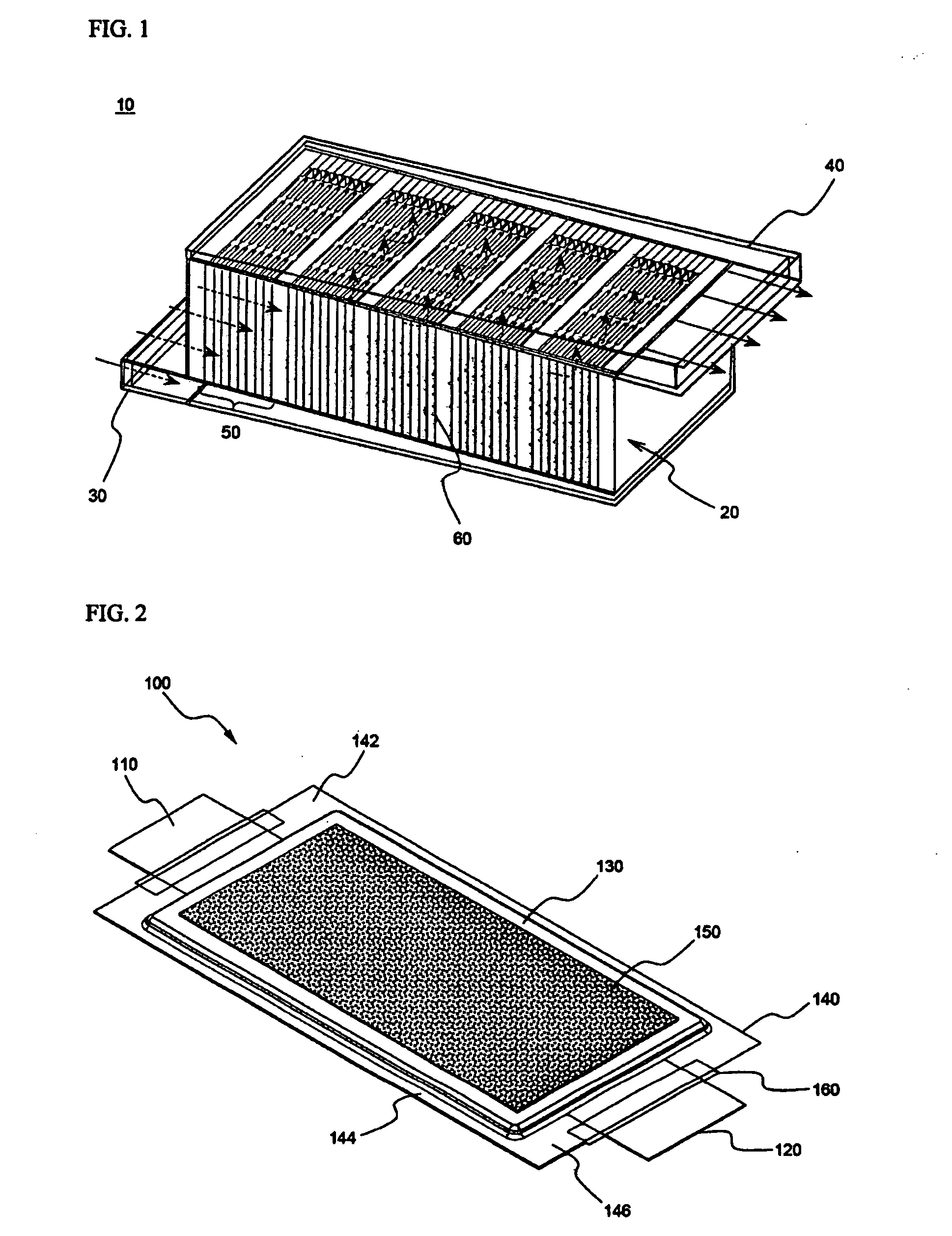
[0049]FIG. 2 is a perspective view typically illustrating a pouch-shaped battery used as a unit cell according to a preferred embodiment of the present invention.

[0050]The pouch-shaped battery 100 is constructed in a structure in which two electrode taps 110 and 120 protrude from the upper end and the lower end of a battery body 130, respectively, while the electrode taps 110 and 120 are opposite to each other. According to circumstances, both the electrode taps 110 and 120 may protrude from the upper end of the battery body 130. A sheathing member 140, as a battery case, comprises upper and lower sheathing parts. That is, the sheathing member 140 is a two-unit member. While an electrode assembly (not shown) is received between the upper and...


PUM

PropertyMeasurementUnit
operating temperatureaaaaaaaaaa
temperatureaaaaaaaaaa

Abstract

Disclosed herein is a middle- or large-sized battery pack including a plurality of unit cells electrically connected with each other, wherein the battery pack is constructed in a structure in which a heat transfer medium flows through gaps defined between the unit cells for controlling the overall temperature of the battery pack to be within a predetermined temperature range for the optimum operation of the battery pack, and each unit cell is provided at the outer surface thereof, at which the heat transfer medium is brought into contact with each unit cell, with a layer containing a phase transformation material (‘phase transformation layer’) for minimizing individual temperature difference between the unit cells. The present invention has the effect of controlling the overall temperature of the battery pack and individual controlling the temperatures of unit cells constituting the battery pack. Also, the present invention has the effect of restraining the abrupt change in temperature of the unit cells, when the battery pack is not in operation or when the external environment abruptly changes, thereby preventing the degradation of the unit cells. Furthermore, the present invention has the effect of minimizing damage to the unit cells due to foreign matter when the foreign matter is brought into contact with the unit cells. In addition, the present invention has the effect of reducing the overall temperature difference of the battery pack and manufacturing a middle- or large-sized battery pack having a compact structure.

Description

CROSS REFERENCE TO RELATED APPLICATIONS[0001]The present application is a national phase entry under 35 U.S.C. §371 of International Application No. PCT / KR2007 / 001588, filed Mar. 31, 2007, published in English, which claims priority from Korean Patent Application No. 10-2006-0029964, filed Apr. 3, 2006. The disclosures of said applications are incorporated by reference herein.FIELD OF THE INVENTION[0002]The present invention relates to a middle- or large-sized battery pack including a dual temperature-controlling system, and, more particularly, to a middle- or large-sized battery pack including a dual temperature-controlling system that is capable of controlling the overall temperature of the battery pack using a heat transfer medium flowing through gaps defined between unit cells of the battery pack and controlling the temperature of each unit cell using a phase transformation layer attached to the outer surface of each unit cell.BACKGROUND OF THE INVENTION[0003]One of the biggest ...

Claims


Application Information

Patent Timeline
Patent Type & Authority Patents(United States)
IPC IPC(8): H01M10/50H01M50/121H01M50/124H01M50/131H01M50/211H01M50/291
CPCH01M2/0277H01M2/1077H01M2/1094H01M10/5004H01M10/5073H01M10/5032H01M10/5059H01M10/5067H01M10/5016H01M10/625H01M10/6563H01M10/647H01M10/6557H01M10/6566H01M10/613H01M10/6555H01M10/617H01M10/659Y02E60/10H01M50/24H01M50/121H01M50/124H01M50/291H01M50/211H01M50/131H01M50/20
Inventor AHN, JAESUNGJUNG, DO YANGNAMGOONG, JOHN E.CHOI, SEUNGDONPARK, SINYOUNG
Owner LG ENERGY SOLUTION LTD
Why Eureka
Try Eureka