Conical swirler for fuel injectors and combustor domes and methods of manufacturing the same

a technology of fuel injectors and swirlers, which is applied in the direction of spray nozzles, combustion processes, lighting and heating equipment, etc., can solve the problems of significant cost improvement, and achieve the effect of reducing the frontal surface area and minimizing the area for carbon formation

Active Publication Date: 2013-01-08
COLLINS ENGINE NOZZLES INC
View PDF40 Cites 25 Cited by
  • Summary
  • Abstract
  • Description
  • Claims
  • Application Information

AI Technical Summary

Benefits of technology

[0018]The present invention is related to a new conical swirler for fuel injectors and combustor domes used in gas turbine engines to impart swirling motion to fuel and air and methods of manufacturing such devices. Unlike conventional axial and radial swirlers, the disclosed conical swirler features a plurality of cut-through slots on a cone-shaped body. The contour and spacing of the slots can be configured and arranged in many different ways to accommodate a wide range of requirements for fluid flow areas and swirl strengths. The cone-shaped swirler of the subject invention fits well into various types of fuel injector nozzles and provides a reduced frontal surface area to minimize area for carbon formation.
[0021]In one aspect of the present invention, the preferred method of forming the slot pattern on the swirler blanks is by wire Electro Discharge Machining (EDM) processing whereby material from the blanks is removed to form the slot pattern. This process presents significant cost improvements over prior manufacturing methods, and results in producing swirlers that perform well in fuel atomization and combustion for gas turbine engine applications.

Problems solved by technology

This process presents significant cost improvements over prior manufacturing methods, and results in producing swirlers that perform well in fuel atomization and combustion for gas turbine engine applications.

Method used


Image

  • Conical swirler for fuel injectors and combustor domes and methods of manufacturing the same
  • Conical swirler for fuel injectors and combustor domes and methods of manufacturing the same
  • Conical swirler for fuel injectors and combustor domes and methods of manufacturing the same

Examples


Embodiment Construction

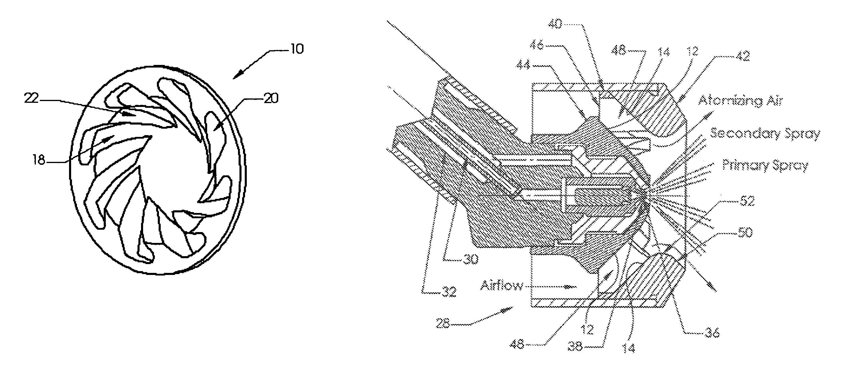
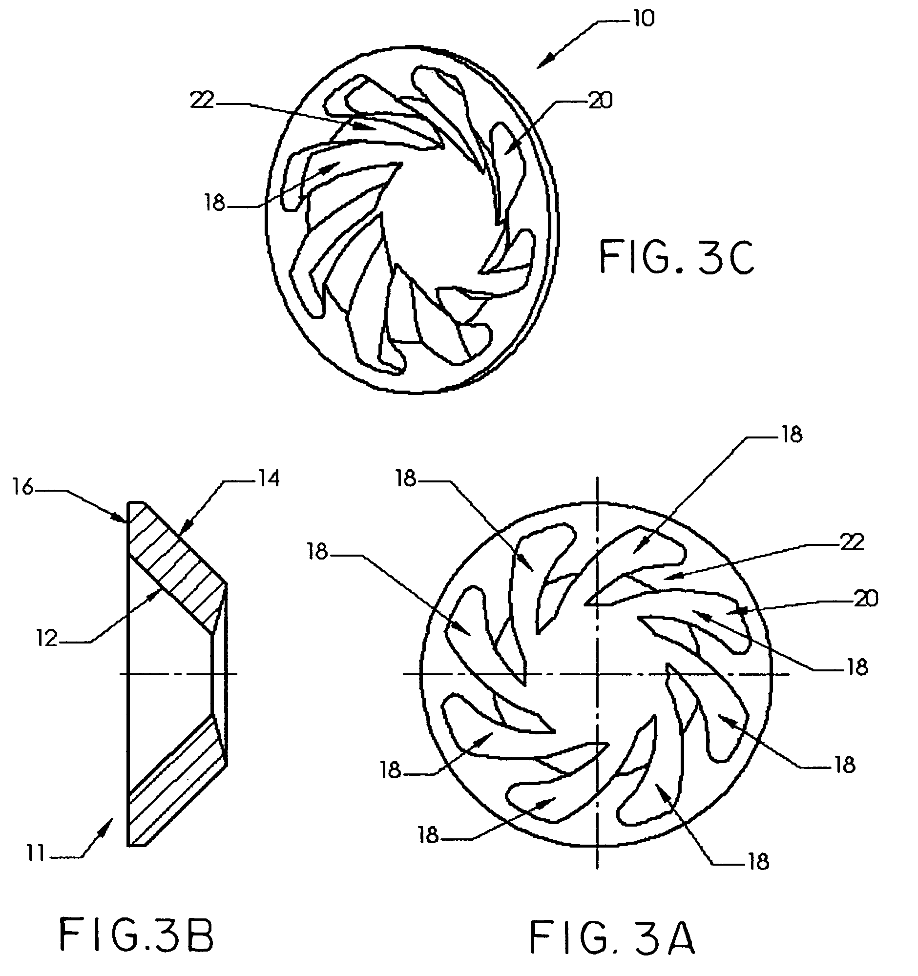
[0042]Referring to FIGS. 3A and 3C, there is shown an illustrative embodiment of an axial-type, conical swirler 10 with aerodynamic turning slots 18 in accordance with a first embodiment of the present invention. Although the following description describes a conical or cone-shaped swirler, the invention is not to be limited thereto as the principles taught work also for disk-shaped and dome-shaped swirler blanks (not shown). The manufactured conical swirler 10 begins as a swirler blank 11 on which a specific slot pattern is formed. The slot pattern consists of a plurality of turning vanes 22 and a corresponding plurality of turning slots 18 that separates each pair of adjacent turning vanes 22. Although FIGS. 3A and 3C show eight turning vanes 22 and eight corresponding turning slots 18, the invention is not to be so limited as the swirler 10 can include fewer or more than eight slots 18 and vanes 22. FIGS. 3A and 3C also show that the dimensions of the slots 18 and the vanes 22 ar...


PUM

PropertyMeasurementUnit
inner diameter radiusaaaaaaaaaa
outer diameteraaaaaaaaaa

Abstract

A method of manufacturing gas and / or fuel swirlers for fuel injectors and combustor domes and cone-shaped swirlers so manufactured are disclosed. The disclosed conical swirlers feature cut-through slots on a cone-shaped body. The contour and spacing of the slots are configured and arranged to accommodate a wide range of requirements for fluid flow areas and swirl strengths. Preferably, the cone-shaped swirlers can be manufactured by wire EDM processing. More preferably, multiple cone-shaped swirlers can be manufactured simultaneously by nesting swirler blanks in a stack and wire EDM processing the stack as a unit. The cone-shaped pinwheel swirler fits well into various fuel injector heads, enabling the injectors to reduce the frontal surface area and flat area for minimal potential of carbon formation.

Description

BACKGROUND OF THE INVENTION[0001]1. Field of the Invention[0002]The present invention relates to fuel injection devices for mixing fuel and compressed air and, more particularly, to fuel injection devices for gas turbine engines that include a conical swirler to impart a swirling motion to dispensed fuel for improved fuel atomization and combustion and to methods of manufacturing such devices.[0003]2. Background of the Related Art[0004]Most fuel injectors, for example, most fuel injectors for gas turbine engines, enhance fuel atomization during engine ignition and combustion sequences using kinetic energy of a flowing air or gas stream to shatter a fuel sheet into fine droplets, which are then introduced into a combustion chamber. Atomization of fuel is desirable because atomized fuel combusts more quickly, more completely, and more cleanly. Some fuel injectors employ air assist atomizers to deliver high pressure, high velocity air from an external source, which is then mixed with f...

Claims


Application Information

Patent Timeline
Patent Type & Authority Patents(United States)
IPC IPC(8): B05B7/10F02C7/00B23H7/06F23D11/10F23R3/14F23R3/28
CPCF23D11/107F23R3/28F23R3/14F23D2213/00Y10T29/49323Y10T29/49826B23H9/10F23R2900/00018F05D2230/10
Inventor MAO, CHIEN-PEISHORT, JOHN
Owner COLLINS ENGINE NOZZLES INC
Why Eureka
Try Eureka